Introduction
Within This Page
While the control of moisture is practically a universal requirement for buildings, the importance of the control of heat transfer tends to become more critical as the severity of climate, either hot or cold, increases. Managing heat flows is critical to occupant thermal comfort, energy efficiency, durability, and increasingly, thermal resilience during periods of extended power outages.
This is the last resource page in a series of related resource pages that present a framework for the application of building science principles to enclosure design. It is recommended that readers are familiar with the concepts and strategies outlined in the resource pages listed below, preferably accessed in the sequence indicated below, before reviewing concepts and strategies that deal with managing enclosure heat flows.
- Building Science Concepts
- Building Enclosure Design Principles and Strategies
- Moisture Management Concepts
- Moisture Management Strategies
Description
This resource page explores the heat transfer mechanisms in buildings and their interactions with the building-as-a-system. Rather than repeating what is available elsewhere, the intention here is to better connect the related WBDG Resource Pages listed above. Principles, concepts, and strategies for heat transfer and air leakage are outlined in the sections that follow, and links to a number of authoritative publications have been provided to access the many means by which heat transfer and air leakage can be managed as part of a whole building strategy for achieving high-performance buildings.
It is important to appreciate that enclosure heat flows involve conduction, convection, and radiation. Heat transfer across the enclosure through opaque enclosure components is primarily due to conduction and convection within wall and roof cavities. The dominant heat transfer mechanism for solar gains through transparent and translucent components, such as windows and skylights, is radiation, but conduction, convection, and radiation all affect heat flows after the sun has set. Air leakage and ventilation represent a significant proportion of the total heat flows across a building enclosure unless an effective air barrier system and ventilation heat recovery are deployed. Understanding the mechanisms driving heat flows enables designers to develop more efficient enclosures cost-effectively by allocating budgets to components that are most critical to high-performance buildings.
Heat Transfer Mechanisms and Models
The role of the building enclosure as a thermal separator involves the control of heat losses and gains. Heat losses and gains are generally categorized into:
- Transmission by conduction, convection, and radiation across the building enclosure; and
- air leakage and ventilation.
In the Introduction it was noted that other available resource pages deal with the control of air leakage and HVAC strategies for heat recovery from ventilation air. The control of air leakage is critical to achieving energy efficiency, comfort, and durability and the provision of a continuous air barrier system should be viewed as an essential strategy for managing heat and moisture flows in buildings. Heat or energy recovery from ventilation air is another critical HVAC strategy for enhancing energy efficiency, but the focus here is on transmission heat losses and gains through enclosures by the mechanisms of conduction, convection, and radiation. After air movement across enclosure assemblies is effectively controlled, transmission losses and gains represent the next most significant design consideration.
Conduction
Thermal conduction involves energy transfer between parts of a continuum in a physical substance. In solids, heat energy is transferred as kinetic energy at the atomic level. The heat is transferred from hotter regions with higher kinetic energy, to cooler regions with lower kinetic energy. As heat is applied to some part of a material, and as it is extracted from another part, a thermal gradient is formed. The thermal gradient is typically measured as a temperature difference across the material. Heat energy transferred in this way is referred to as conductive heat transfer, the primary mechanism in solid, opaque building materials.
The conductive heat flow through a material depends on the magnitude of the temperature difference across the material, its area, the thickness of the material, and the material's thermal conductivity. Thermal conductivity is a measure of the ability of a material to conduct heat. For a given thickness of material, its ability to conduct heat is termed the thermal conductance. Building materials and insulation are often specified and labeled by their resistance to heat transfer. This is simply the reciprocal of the thermal conductance. The resistance to heat transfer for a material is often referred to as its R-value. Energy codes are increasingly based on U-values, rather than R-values, of entire enclosure assemblies.
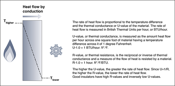
Figure 1: Heat flow by conduction occurs in all materials that are exposed to a temperature difference across them. Good insulators resist the flow of heat by conduction. Photo Credit: T. Kesik
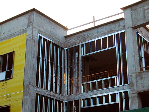
Figure 2: Prior to detailed studies of thermal bridging in building enclosure assemblies, designers did not pay attention to heat flow by conduction through steel studs and reinforced concrete structures that did not benefit from continuous exterior insulation. Photo Credit: T. Kesik
Convection
Convection is the transfer of heat between a solid or a fluid, and a moving fluid (a liquid or a gas). The force that moves the fluid can be gravitational (natural convection), as in the case of buoyancy forces (for example, rising hot air), or it can be mechanical (forced by a fan, for example). Convection is actually a form of conductive heat transfer. The exchange of energy between the fluid or gas, and another solid, fluid, or gas occurs during the brief period of contact, when the energy is transferred by conduction. The liquid or gas, however, moves quickly away from the point of contact physically transferring energy.
Natural and forced convection (by fan or pump) describe a great number of phenomena: the weather and winds result from natural convection within the earth's atmosphere. The heat transferred across air spaces, as in the case of wall cavities and multi-pane windows, is another example of natural convection. The delivery of heat by a forced air furnace is a common example of forced convection. The convective exchanges in rooms, between walls, windows, ceiling, and floor, are now recognized as important comfort considerations. Convective heat transfer across the building enclosure is largely controlled by the provision of air barriers and to a lesser extent by the maintenance of uniform interior surface temperatures.
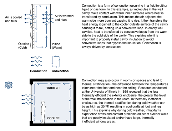
Figure 3: Convective heat transfer occurs in enclosure cavities unless they are properly insulated. The same phenomenon occurs in rooms with thermally inefficient exterior enclosures, setting up drafts as room air is cooled, especially by large glazed areas, falls and flows along the floor at the outside perimeter. High floor-to-ceiling temperature stratification is an indicator of a thermally inefficient wall enclosure. Photo Credit: T. Kesik
Figure 4: The use of expansive spray foam insulation materials is a good strategy for areas of the building enclosure that are difficult to air-seal and insulate properly. Photo Credit: T. Kesik
Radiation
Radiative heat transfer is an interaction between objects at different temperatures. All objects lose energy continuously by emitting electromagnetic radiation and gain energy by absorbing electromagnetic energy from around them. No medium is required between an object which emits radiation and one which receives it. The energy transferred is simply a function of the absolute temperature difference between the two objects.
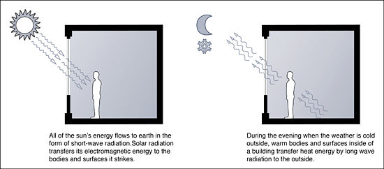
Figure 5: Heat transfer by radiation is responsible for solar gains which cause discomfort when they are excessive. Radiative heat loss at night can cause inhabitants to feel a chill. Controlling radiative heat transfer is critical to maintaining thermal comfort in buildings. Photo Credit: T. Kesik
Objects at different temperatures will emit radiation of different wavelengths. The sun being very hot emits essentially short wave radiation, whereas relatively cooler objects on earth tend to emit long wave radiation. This distinction is important particularly as it relates to the use of low-emissivity coatings on glass to both retain heat energy in a building and reject it from warm outdoor surfaces radiating toward the building. Radiative heat loss is also associated with the discomfort sometimes experienced when sitting near cold surfaces, such as large single-glazed windows in winter.
As noted earlier, all three mechanisms of heat transfer occur in real buildings. But these are not the only mechanisms of heat transfer. The latent heat of evaporation and condensation associated with phase changes in liquids and gases, is not normally considered in the modelling of building assemblies for thermal performance; however latent heat transfer is considered in hygrothermal analysis to accurately assess the interactions between heat and moisture in constituent materials.
Heat Transfer Modeling
For the design of comfortable and energy efficient buildings, conduction, convection, and radiation can be accurately modeled. In the past, before the widespread availability of computing, simple methods of calculating heat transfer were employed by building designers, typically in the form of 1-dimensional heat flow models. Starting several decades ago, 2-dimensional analysis was applied to heat flow analysis through window frames and similar types of assemblies, but within the past decade or so, 3-dimensional finite element modelling of complete building assemblies such as walls, windows, and roofs is available to practitioners.
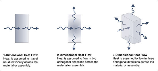
Figure 6: The 3-dimensional modelling of heat flow is the only means of accurately determining the effective thermal resistance of building assemblies, by taking into account thermal bridging effects. Photo Credit: T. Kesik
As a result of more detailed study of how heat moves through real buildings, the significance of thermal bridging across building assemblies is now widely recognized and techniques for minimizing the reduction in insulation effectiveness have been developed and continue to be refined. Traditional building assemblies may have been durable but they are not thermally efficient. Looking at Figure 7, the widespread use of steel studs and cladding attachments in exterior wall assemblies introduces a highly conductive material that causes thermal bridging. Avoiding assemblies that compromise the overall effective thermal resistance requires careful selection, arrangement, and detailing of components.
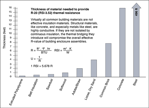
Figure 7: Insulation is orders of magnitude more thermally efficient than common building materials, and should be intelligently employed in the design of high-performance building enclosures. Photo Credit: T. Kesik
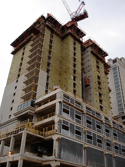
Figure 8: Continuous insulation placed over a reinforced concrete structure is an effective means of achieving a highly durable and energy efficient building enclosure. To achieve the same effective thermal resistance in the wall areas with steel studs, more insulation and careful detailing will be required. Photo Credit: T. Kesik
Insulation Effectiveness and Thermal Bridging
In the past, requirements for thermal insulation were often expressed as nominal R-values for various enclosure assemblies. For assemblies made with highly conductive materials, such as steel stud walls, field observations and infrared thermography indicated extensive thermal bridging. More recently, researchers have been able to model and quantify the impacts of thermal bridging on the overall thermal effectiveness of enclosure assemblies.
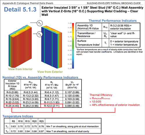
Figure 9: Recent research has catalogued the performance of typical enclosure assemblies and indicates that many conventional assemblies are thermally inefficient and provide unacceptable levels of insulation effectiveness due to thermal bridging. Building Envelope Thermal Bridging Guide, Version 1.1 by Morrison Hershfield Ltd., Vancouver BC: April 2016Download building-envelope-thermal-bridging-guide-1.1.pdf
The results of this research have been published and disseminated and an example of thermal analysis is shown in Figure 9. 1As was widely suspected, the composition of enclosure assemblies and methods of cladding attachment result in thermal bridging that significantly compromises the insulation effectiveness.
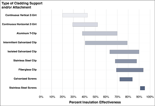
Figure 10: Percent effectiveness of exterior insulation with various cladding support systems and typical thicknesses of exterior insulation (2" to 8" ranging from R-8 to R-40). Photo Credit: Cladding Attachment Solutions for Exterior Insulated Commercial Walls. Graham Finch and James Higgins, RDH Technical Bulletin No. 011, December 2015.
In Figure 10, the range of effectiveness values for the various methods of cladding support and/or attachment result from different substrates, spacing's, and sheet metals. It is apparent that traditional techniques, such as Z-girts, can at best achieve about 50% exterior insulation effectiveness, essentially requiring double the thickness of exterior insulation to achieve an effective thermal resistance that approaches the nominal value. It should be noted that the ranges of percent insulation effectiveness depicted in Figure 10 capture different spacing for attachment members. Heavier cladding or cladding on tall buildings with high wind loads will have girts, clips, or screws closer together—this will result in performance at the lower end of the percent insulation effectiveness range.
High-performance buildings require high-performance enclosures that manage heat flows effectively. The proper selection, arrangement, detailing, and integration of enclosure components and assemblies to maintain the continuity of thermal insulation and the air barrier system are no longer best practices but standard practices needed to comply with codes and standards. A number of guides for incorporating these best practices are now available and a wide range of products exist to enable the design and construction of high-performance enclosures.
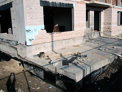
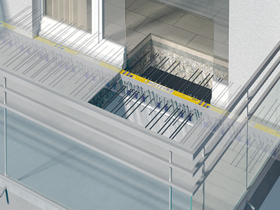
Figure 11: Continuous rigid insulation installed over a masonry backup wall represents an energy-efficient and resilient building enclosure provided the windows are thermally efficient and not too large in area. Photo Credit: T. Kesik
Figure 12: Thermal breaks for cantilevered reinforced concrete balcony slabs eliminate a significant source of thermal bridging and improve thermal comfort. Photo Credit: Schöck USA Inc.
Recommended Effective Thermal Resistance Values For Enclosures
As requirements for energy efficiency become more demanding, the primary role of the enclosure is becoming recognized as the most cost-effective means of attaining high-performance targets. Table 1 indicates recommended effective R-values for various enclosure components for use in residential buildings. It is important to note these are effective R-values that account for thermal bridging effects.
TABLE 1
| Climate Zone | Wall | Vented Attic | Compact Roof | Basement Wall | Exposed Floor | Slab Edge | Windows (U/SHGC) | Sub-slab |
|---|---|---|---|---|---|---|---|---|
| 1 | 10 | 40 | 35 | 5 | 10 | none | 0.60 / < 0.25 | none |
| 2 | 15 | 50 | 40 | 10 | 20 | 5 | 0.35 / < 0.25 | none |
| 3 | 20 | 50 | 45 | 10 | 20 | 7.5 | 0.30 / < 0.3 | 5 |
| 4 | 25 | 60 | 45 | 15 | 30 | 7.5 | 0.30 / < 0.35 | 7.5 |
| 5 | 30 | 65 | 50 | 15 | 30 | 10 | 0.24 / < 0.50 | 7.5 |
| 6 | 35 | 75 | 60 | 20 | 40 | 10 | 0.18 / --- | 10 |
| 7 | 40 | 90 | 65 | 25 | 45 | 15 | 0.15 / --- | 15 |
| 8 | 50 | 100 | 75 | 35 | 50 | 20 | 0.15 / --- | 20 |
Table 1. Recommended R-values by Climate Zone for High-performance Residential Construction. " --- " Indicates any available solar heat gain coefficient (SHGC) is acceptable, but higher values are preferred.
Source: Building America Special Research Project: High R-Value Enclosures for High-performance Residential Buildings in All Climate Zones.
Table 2 indicates slightly lower effective R-values for the same components in steel-frame commercial buildings. The lower R-values reflect building physics in that the thermal metabolisms of most commercial buildings are internal load dominated as a result of internal heat gains from people, lighting, and equipment. As a result, levels of thermal insulation in Table 2 are balanced between heating and cooling demands, but this balance will shift as lighting and office equipment become much more energy efficient.
TABLE 2
| Climate Zone | Wall | Vented Attic | Compact Roof | Basement Wall | Exposed Floor | Slab Edge | Windows (U/SHGC) | Sub-slab |
|---|---|---|---|---|---|---|---|---|
| 1 | 10 | 30 | 15 | 5 | 10 | none | 1.20 / < 0.25 | none |
| 2 | 10 | 40 | 20 | 5 | 20 | 5 | 1.20 / < 0.25 | 7.5 |
| 3 | 15 | 40 | 20 | 5 | 20 | 7.5 | 0.60 / < 0.25 | 10 |
| 4 | 20 | 40 | 20 | 5 | 30 | 7.5 | 0.40 / < 0.4 | 15 |
| 5 | 20 | 40 | 20 | 5 | 30 | 10 | 0.35 / < 0.4 | 15 |
| 6 | 20 | 40 | 20 | 10 | 30 | 10 | 0.35 / < 0.4 | 15 |
| 7 | 20 | 40 | 20 | 10 | 30 | 15 | 0.35 / --- | 20 |
| 8 | 20 | 50 | 20 | 10 | 40 | 20 | 0.35 / --- | 20 |
Table 2. Recommended R-values by Climate Zone for High-performance Residential Construction. " --- " Indicates any available solar heat gain coefficient (SHGC) is acceptable, but higher values are preferred.
Source: ASHRAE 90.1.
Performance paths in many energy codes permit the use of much lower levels of thermal insulation by trading off energy efficient lighting and HVAC equipment against the enclosure efficiency. This tends to result in buildings with larger sized HVAC equipment and enclosures that are often uncomfortable during extreme weather, hot and cold. There is an increasing awareness among the building science community that observing appropriate levels of insulation, as indicated in Tables 1 and 2, is a cost-effective means of achieving high-performance buildings that are more comfortable, robust, and resilient.
Achieving exterior walls with higher effective R-values can be challenging because they become thicker as more insulation is added, and require different details for cladding attachment, structural penetrations, window trim, etc. When exterior walls with higher effective R-values are desired, or required by codes, these may be achieved by placing all of the insulation to the exterior of the wall structure and air barrier plane, or by placing insulation both within the wall cavity and the exterior. However, the ratio of exterior to interior insulation must be observed as indicated in Table 3 in order to manage the risk of condensation inside the wall. Table 3 replaces the outdated one-third / two-thirds rule of thumb for the ratio of exterior to interior insulation.
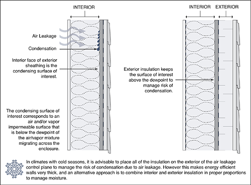
Figure 13. Exterior insulation improves the thermal efficiency of walls but also help manage moisture problems due to air leakage in cold climates.
TABLE 3
| Indoor | RH | 20% | 25% | 30% | 35% | 40% | 50% | 60% | |
|---|---|---|---|---|---|---|---|---|---|
| Dew Point | °C | -3.0 | 0.0 | 2.5 | 4.7 | 6.6 | 9.9 | 12.7 | |
| °F | 26.6 | 32.0 | 36.6 | 40.5 | 44 | 49.9 | 54.8 | ||
| T-outdoor | °C | °F | Ratio of Exterior to Interior Insulation | ||||||
| 0 | 32 | 0.00 | 0.00 | 0.12 | 0.23 | 0.32 | 0.47 | 0.60 | |
| -5 | 23 | 0.08 | 0.19 | 0.29 | 0.37 | 0.45 | 0.57 | 0.68 | |
| -10 | 14 | 0.23 | 0.32 | 0.40 | 0.48 | 0.54 | 0.64 | 0.73 | |
| -15 | 5 | 0.33 | 0.42 | 0.49 | 0.55 | 0.60 | 0.69 | 0.77 | |
| -20 | -4 | 0.41 | 0.49 | 0.55 | 0.60 | 0.65 | 0.73 | 0.80 | |
| -25 | -13 | 0.48 | 0.54 | 0.60 | 0.65 | 0.69 | 0.76 | 0.82 | |
| -30 | -22 | 0.53 | 0.59 | 0.64 | 0.68 | 0.72 | 0.78 | 0.84 | |
| -35 | -31 | 0.57 | 0.63 | 0.67 | 0.71 | 0.74 | 0.80 | 0.85 | |
| -40 | -40 | 0.61 | 0.66 | 0.70 | 0.73 | 0.76 | 0.82 | 0.86 | |
| Based on the work of Dr. John Straube, P. Eng. in High Performance Enclosures, Building Science Press (2012). | |||||||||
An example of how to apply Table 3 is shown in Figure 14 for a typical steel stud wall assembly that uses horizontal metal Z-girts installed over top of an exterior sheathing and fastened to the vertical steel studs beneath. It is important to appreciate that while the potential for condensation has been properly managed, the overall effective thermal resistance of the wall is only R-14.3, significantly less than the nominal thermal resistance of the insulation layers, i.e., 20 + 10.8 = R-30.8.
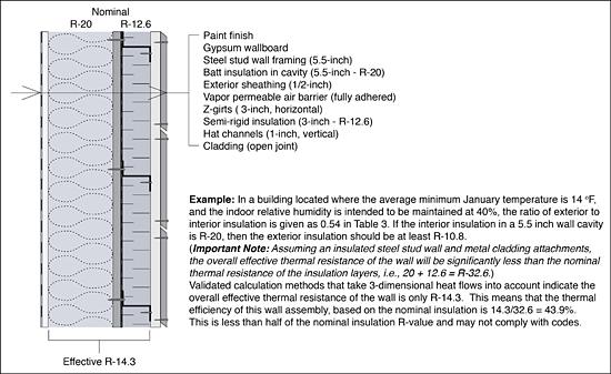
Figure 14. Recent research indicates that methods of construction and cladding attachment can significantly compromise the overall effective thermal resistance of exterior walls.
It is important to note that in the example in Figure 14, if the stud wall cavity was not insulated, the R-12.6 exterior insulation would provide an effective thermal resistance of about R-9. This means that only R-5.3 of the R-20 cavity insulation is realized due to thermal bridging through the steel studs. But it should also be carefully noted that almost an additional 5 inches of exterior insulation would have to be added to the 3 inches indicated in Figure 14 for a total of 8 inches, in order to achieve an R-14.3 overall effective thermal resistance when using horizontal Z-girts. Thermally, there is not an appreciable benefit in placing all of the insulation on the exterior and it may make cladding attachment and window installation more difficult and costly. This reinforces the important of selecting thermally efficient cladding attachments such that a higher percentage insulation effectiveness may be realized.
Exterior wall assemblies typically account for the largest surface area of any of the other building enclosure assemblies (i.e., roofs, floors over unconditioned spaces, etc.). As a result of higher effective R-values required by energy codes, the insulated, opaque wall assemblies have become more expensive, but the enhanced energy efficiency they provide remains a cost-effective investment. However, this investment in energy efficient walls can be significantly compromised by a combination of inefficient windows and/or large window areas that reduce the overall effective thermal resistance of the building enclosure.
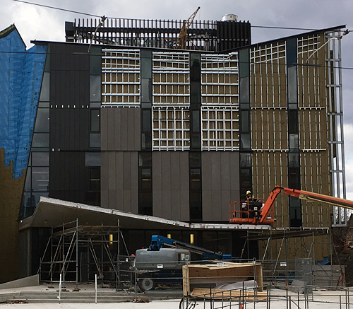
Figure 15: The excessive use of steel cladding attachments can significantly reduce the overall effective R-value of opaque wall assemblies. It is important to ensure that measures to effectively manage moisture and air leakage are not undone by thermally inefficient opaque wall assemblies. Photo Credit: T. Kesik
A critical consideration in the design of building facades is the window-to-wall ratio (WWR) because it influences the overall effective thermal resistance of the exterior wall enclosure. Too little glazing will reduce opportunities for daylighting and views, and too much glazing makes it difficult to achieve high-performance in terms of comfort, energy efficiency, and resilience. Figure 16 indicates the resulting overall effective thermal resistance of wall enclosures for various combinations of opaque wall R-values and window/glazing U-values. Note that in all cases, the R-values and U-values are effective values that account for thermal bridging, transitions and edge effects, as discussed in the previous section.
Important Terminology Note: The term "exterior wall enclosure" refers to the total exterior wall area including all opaque assemblies, windows and glazing.
Exterior Wall Enclosure Area = Opaque Walls Area + Windows/Glazing Area
Window-to-Wall Ratio (WWR) = Windows/Glazing Area / Exterior Wall Enclosure Area
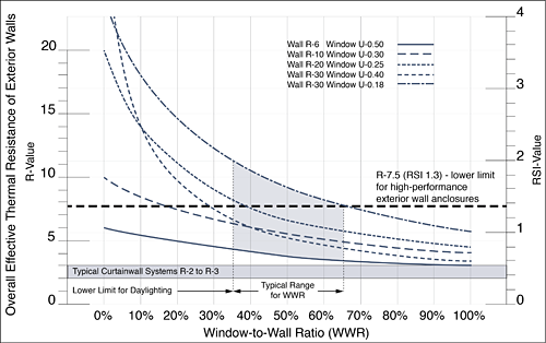
Figure 16. Influence of window-to-wall ratio on wall enclosure overall effective R-value for various combinations of opaque walls and windows.
There are several observations worth noting in Figure 16:
- Fully glazed building facades using conventional curtainwalls and window walls are too inefficient to achieve.
- For anything higher than a 10% WWR, an R-20 opaque wall with U-0.25 windows outperforms an R-30 opaque wall with U-0.40 windows. The practical upper limit of thermal efficiency for wall enclosures is mostly determined by the thermal efficiency of the windows.
- For anything higher than a 40% WWR, an R-10 opaque wall with U-0.30 windows outperforms an R-30 opaque wall with U-0.40 windows. For typical ranges of WWR ratios in buildings, investments in more efficient windows deliver higher performance than investments in more efficient opaque walls.
- To achieve high-performance exterior walls over typical ranges of WWR, opaque walls should have a minimum effective thermal resistance value of R-25 and windows should have an effective U-value no greater than U-0.25.
- The lower limit of R-7.5 for exterior wall enclosures applies to hot and cold climate zones and takes into account comfort, energy efficiency, thermal resilience and the ability of low temperature / low intensity heating and cooling technologies to be effectively deployed.
The physics behind the lower limit of approximately R-7.5 for the overall effective thermal resistance of exterior wall enclosures is explained in Figure 17.
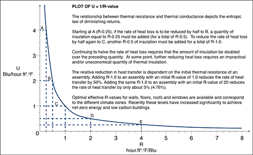
Figure 17. The optimal overall effective R-value of the entire building enclosure is more important than the amount of insulation provided in specific components, such as walls or roofs. In most climate zones, the high-performance threshold for the overall effective R-value of exterior wall enclosures is the same as the entire building enclosure, at around R-7.5. This means that walls, roofs, and exposed floors will have to be insulated to levels much higher than this overall threshold to compensate for the lower R-values associated with windows. Beyond this level, the benefits are marginal (diminishing returns) and it is usually more cost-effective to improve the energy efficiency of other aspects of the building-as-a-system.
In general, high-performance buildings are more easily achieved when the WWR is maintained between 40-50%, and it is generally acknowledged that going beyond 65% results in what is termed a high-cholesterol building2 that is overly dependent on active systems rather than enjoying passive performance provided by the enclosure.
As indicated in Figure 18, the enclosure moderates between the exterior environment and the narrow range of human body and thermal comfort temperatures. Active systems can only supplement the amount of heating, cooling, and ventilation that is needed—they cannot fulfill the role of passive systems that actually moderate the heating and cooling demands.
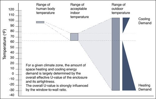
Figure 18. It is now recognized that the passive performance of the enclosure is what most cost-effectively delivers energy savings and thermal comfort in buildings because it moderates heating and cooling energy demands.
While the goals of inhabitant comfort, energy efficiency, and durability will always guide building design, additional considerations related to thermal efficiency are emerging. Aging infrastructure, extreme weather events, and manmade disasters may require buildings to become more autonomous and resilient.
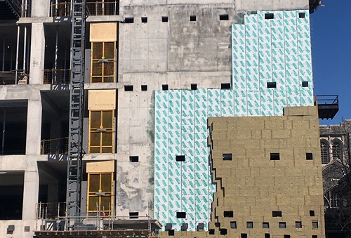
Figure 19. It is now recognized that the passive performance of the enclosure is what most cost-effectively delivers energy savings and thermal comfort in buildings because it moderates heating and cooling energy demands.
Thermal Autonomy and Thermal Resilience
The management of enclosur heat flows is key to extending thermal autonomy and achieving thermal resilience in buildings. Thermal autonomy is a measure of the fraction of time during a typical year when a building can passively maintain comfort conditions without active system energy inputs. Thermal resilience is a measure of how long inhabitants may remain in their dwellings during extreme weather events that coincide with extended power outages disabling active systems for space heating and cooling.
It is worth noting that thermal resilience is among many aspects of passive survivability, a term that refers to the building's ability to maintain critical life-support conditions in the event of extended loss of power, heating fuel, or water3.
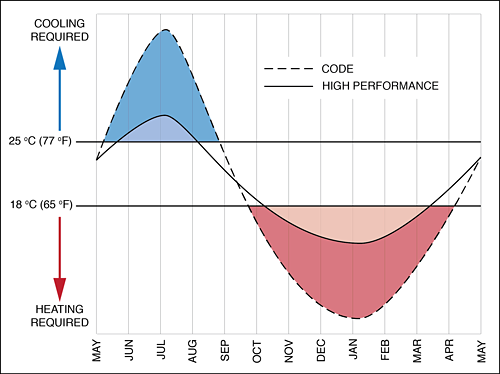
Figure 20. Improving the thermal efficiency of enclosures increases thermal autonomy, conserves energy, and reduces the capacity of heating and cooling equipment while extending its service life. In most climate zones, it is feasible to increase thermal autonomy from about 30% for a code minimum building to well over 70% for a high-performance building.
Thermal autonomy is often represented as the fraction of time the building experiences active space heating and cooling energy demands. A completely thermally autonomous building that requires no heating or cooling whatsoever would have a rating of 100% (i.e., its indoor temperature would remain between 65oF and 77oF year round). In Figure 20, the building constructed to code minimum requirements for energy efficiency has a thermal autonomy of about 30% based on equipment run times, while the high-performance building enjoys about 70% thermal autonomy. The areas under and over the demand curves indicate the amount of heating and cooling energy, respectively. Figure 20 indicates the high-performance building yields about an 80% reduction in annual energy demands for space heating and cooling. Two important aspects of building performance emerge from this comparison.
- First, the capacities of the heating and cooling equipment for the high-performance building are much smaller than for the code building. Piping and ductwork will likely be correspondingly smaller and less intrusive.
- Second, the run times of the equipment serving the high-performance building will be lesser than for the code building. This translates into longer service life and lower maintenance costs.
It is important to capture the synergistic relationships between high-performance enclosures and HVAC systems to properly assess cost-effectiveness. Another important characteristic of high-performance enclosures is their contribution towards thermal resilience. During extended power outages corresponding to extreme weather—both cold and hot—buildings with thermally inefficient enclosures cannot maintain comfortable conditions for more than a day or two, and then become so unbearable the inhabitants are forced to evacuate their dwellings.
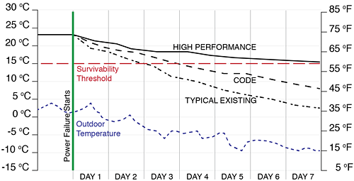
Figure 21. High-performance enclosures retain heat for longer periods of time than less insulated and airtight buildings. Research indicates they also keep the heat out during heat waves and moderate peak indoor temperatures. Climate change is causing an increase in the frequency and severity of extreme weather events making thermal resilience an important design consideration.
Data Source: Baby It's Cold Outside, Urban Green Council, U.S. Green Building Council of New York, 20144.
A building that is designed to provide thermal resilience will provide a week or more of comfortable indoor conditions, usually sufficient time to have power restored. With today's sophisticated energy modelling software, buildings can be designed to take thermal resilience into account. 5Holistic approaches to design for thermal resilience also take into account the need for external shading devices to block excessive solar gains and provide effective natural ventilation to provide free cooling during heat waves6.
Thermal autonomy and thermal resilience are interrelated. The same enclosure characteristics that extend thermal autonomy also help achieve higher levels of thermal resilience. Active systems cannot extend the thermal autonomy and resilience of buildings—they can only supplement the energy deficits that cannot be covered by passive systems.
Strategies for Managing Enclosure Heat Flows
The control strategies for heat transfer and air leakage are far fewer than those involved in the control of moisture migration. They are, however, related to one another because the control of heat transfer and air leakage impact the management of condensation within building enclosures. The basic strategies for managing enclosure heat flows include:
- A continuous, structurally supported air barrier system to control air leakage.
- Continuous thermal insulation with minimal thermal bridging to achieve high effective R-values.
- A window-to-wall ratio that does not compromise the overall effective R-value of the enclosure and provides a balance between daylighting and energy efficiency.
- Sizing and arrangement of operable windows to promote natural ventilation.
- Selection of windows with spectrally selective glazing that are properly detailed and integrated with the air barrier system.
- Integration of shading devices that can be controlled to take advantage of passive solar gains during cold weather and avoid overheating and visual glare during hot weather.
- Heat or energy recovery from ventilation air to reduce space heating and cooling energy demands.
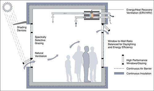
Figure 22. The basic strategies depicted above for managing enclosure heat flows are effective in all climate zones. When these strategies are optimally integrated, the result is a cost-effective building that provides a healthful and comfortable indoor environment.
The building science behind managing enclosure heat flows is fully developed and readily applicable through a broad range of products and building enclosure system alternatives. Software to assess the hygrothermal performance of various components, such as walls and roofs, has been developed and technical professionals have been trained it its proper application. The energy performance of both the passive and active systems in buildings can now be accurately modelled to better inform the integrated design process. Enclosures have never been more achievable, durable, and affordable.
Additional Resources
Publications
- Air Barrier Systems for Low- and Mid-Rise Commercial and Residential BuildingsDownload Technical_Guide_DELTA-VENT_SA_Jan-2015.pdf by Cosella-Dörken Products Inc., Beamsville ON Canada, March 2016
- Air Flow Control in Buildings by John Straube, Building Science Digest 014, Building Science Press, 2007
- Building Envelope Thermal Bridging GuideDownload building-envelope-thermal-bridging-guide-1.1-appendix-a.pdf Appendix A—Catalogue Material Data Sheets—Version 1.1
- Building Envelope Thermal Bridging GuideDownload building-envelope-thermal-bridging-guide-1.1-appendix-b.pdf Appendix B—Catalogue Thermal Data Sheets—Version 1.1
- Building Envelope Thermal Bridging GuideDownload building-envelope-thermal-bridging-guide-1.1.pdf Version 1.1 by Morrison Hershfield Ltd. Vancouver BC: April 2016
- Cladding Attachment Solutions for Exterior Insulated Commercial WallsDownload TB-11-Cladding-Attachment-Solutions-Web-Reduced.pdf by Graham Finch and James Higgins. RDH Technical Bulletin No. 011, December 2015
- Commercial New Construction by BC Hydro, Power Smart
- Comparing Insulation Types by NAIMA Canada, October 2016
- High Performance Enclosures by John Straube, Building Science Press, February 2012
- MURB Design Guide—Enhancing the Liveability and Resilience of Multi-Unit Residential BuildingsDownload MURB-Design-Guide-v1.0-Jan2017.pdf by T. Kesik and W. O'Brien. 2017
- Thermal Control in Buildings by John Straube, Building Science Digest 011, Building Science Press, (Updated 2011-12-12)
- Real R-Value of Exterior Insulated Wall Assemblies by Mark Lawton, P. Roppel, D. Fookes, A. Teasdale St. Hilaire, and D. Schoonhoven. Building Envelope Science and Technology 1 Conference (Building for Energy Efficiency and Durability at the Crossroads), Minneapolis MN: June 10-12, 2008
- Field Monitoring and Simulation of a Historic Mass Masonry Building Retrofitted with Interior Insulation by Ueno, K., J. Straube and R. Van Straaten. Thermal Performance of the Exterior Envelopes of Whole Buildings XII International Conference, 2013*
- Measure Guideline: Internal Insulation of Masonry WallsDownload 54163.pdf by Straube, J.F., K. Ueno, and C.J. Schumacher. Energy Efficiency and Renewable Energy, U.S. Department of Energy, July 2012*
- Measuring the Impact of Interior Insulation on Solid Masonry Walls in a Cold Climate by Wilkinson, J., D. De Rose, J.F. Straube and B. Sullivan. 12th Canadian Conference on Building Science and Technology, Montreal, Canada: 2009*
- Performance Evaluation of Retrofitted Solid Masonry Exterior WallsDownload 65033.pdf by Goncalves, Mario, D. CMHC Research Highlight, March 2007*
- Towards a Limit States Approach to Insulating Solid Masonry WallsDownload B6-7-a.pdf by De Rose, D., N. Pearson, P. Mensinga, and J.F. Straube. 14th Canadian Conference on Building Science and Technology, pp. 521-530, Toronto, Canada: October 28-30, 2014*
- Retrofit with Interior Insulation on Solid Masonry Walls in Cool Temperate Climates—An Evaluation of the Influence of Interior Insulation Materials on Moisture Condition in the Building Envelope by SP Bjarløv, S.P., G.R.Finkenand T. Odgaard. Energy Procedia, Volume 78, November 2015, pp. 1461-1466*
*There is a growing trend to retrofit and re-purpose existing buildings with solid masonry enclosures, and the resources listed below provide guidance on how to manage heat and moisture to achieve higher levels of energy efficiency without compromising the durability of the masonry or promoting the growth of mold.
References
- 1Building Envelope Thermal Bridging GuideDownload building-envelope-thermal-bridging-guide-1.1.pdf Version 1.1 by Morrison Hershfield Ltd., Vancouver BC: April 2016.
- 2High Cholesterol BuildingsDownload high_cholesterol_envelopes.pdf by Urban Green Council, U.S. Green Building Council of New York, 2014.
- 3Environmental Building News, Volume 14, Number 12, December 2005.
- 4Baby It's Cold Outside by Urban Green Council, U.S. Green Building Council of New York, 2014.
- 5Simulation-Based Evaluation of High-Rise Residential Building Thermal Resilience by O'Brien, Liam and Isis Bennet. ASHRAE Transactions, Volume 122, Part 1, 2016.
- 6The Influence of Passive Measures on Building Energy Demands for Space Heating and Cooling in Multi-Unit Residential Buildings by Ozkan, A., T. Kesik and W. O'Brien. Proceedings of the eSim 2016 Building Performance Simulation Conference, McMaster University, Hamilton, Ontario, Canada: 2016.
A critical consideration in the design of building facades is the window-to-wall ratio (WWR) because it influences the overall effective thermal resistance of the exterior wall enclosure. Too little glazing will reduce opportunities for daylighting and views, and too much glazing makes it difficult to achieve high-performance in terms of comfort, energy efficiency, and resilience. Figure 16 indicates the resulting overall effective thermal resistance of wall enclosures for various combinations of opaque wall R-values and window/glazing U-values. Note that in all cases, the R-values and U-values are effective values that account for thermal bridging, transitions and edge effects, as discussed in the previous section.
Important Terminology Note: The term "exterior wall enclosure" refers to the total exterior wall area including all opaque assemblies, windows and glazing. Exterior Wall Enclosure Area = Opaque Walls Area + Windows/Glazing Area Window-to-Wall Ratio (WWR) = Windows/Glazing Area / Exterior Wall Enclosure Area

Figure 16. Influence of window-to-wall ratio on wall enclosure overall effective R-value for various combinations of opaque walls and windows.
There are several observations worth noting in Figure 16:
- Fully glazed building facades using conventional curtainwalls and window walls are too inefficient to achieve.
- For anything higher than a 10% WWR, an R-20 opaque wall with U-0.25 windows outperforms an R-30 opaque wall with U-0.40 windows. The practical upper limit of thermal efficiency for wall enclosures is mostly determined by the thermal efficiency of the windows.
- For anything higher than a 40% WWR, an R-10 opaque wall with U-0.30 windows outperforms an R-30 opaque wall with U-0.40 windows. For typical ranges of WWR ratios in buildings, investments in more efficient windows deliver higher performance than investments in more efficient opaque walls.
- To achieve high-performance exterior walls over typical ranges of WWR, opaque walls should have a minimum effective thermal resistance value of R-25 and windows should have an effective U-value no greater than U-0.25.
- The lower limit of R-7.5 for exterior wall enclosures applies to hot and cold climate zones and takes into account comfort, energy efficiency, thermal resilience and the ability of low temperature / low intensity heating and cooling technologies to be effectively deployed.
The physics behind the lower limit of approximately R-7.5 for the overall effective thermal resistance of exterior wall enclosures is explained in Figure 17.

Figure 17. The optimal overall effective R-value of the entire building enclosure is more important than the amount of insulation provided in specific components, such as walls or roofs. In most climate zones, the high-performance threshold for the overall effective R-value of exterior wall enclosures is the same as the entire building enclosure, at around R-7.5. This means that walls, roofs, and exposed floors will have to be insulated to levels much higher than this overall threshold to compensate for the lower R-values associated with windows. Beyond this level, the benefits are marginal (diminishing returns) and it is usually more cost-effective to improve the energy efficiency of other aspects of the building-as-a-system.
In general, high-performance buildings are more easily achieved when the WWR is maintained between 40-50%, and it is generally acknowledged that going beyond 65% results in what is termed a high-cholesterol building2 that is overly dependent on active systems rather than enjoying passive performance provided by the enclosure.
As indicated in Figure 18, the enclosure moderates between the exterior environment and the narrow range of human body and thermal comfort temperatures. Active systems can only supplement the amount of heating, cooling, and ventilation that is needed—they cannot fulfill the role of passive systems that actually moderate the heating and cooling demands.

Figure 18. It is now recognized that the passive performance of the enclosure is what most cost-effectively delivers energy savings and thermal comfort in buildings because it moderates heating and cooling energy demands.
While the goals of inhabitant comfort, energy efficiency, and durability will always guide building design, additional considerations related to thermal efficiency are emerging. Aging infrastructure, extreme weather events, and manmade disasters may require buildings to become more autonomous and resilient.

Figure 19. It is now recognized that the passive performance of the enclosure is what most cost-effectively delivers energy savings and thermal comfort in buildings because it moderates heating and cooling energy demands.
Thermal Autonomy and Thermal Resilience
The management of enclosur heat flows is key to extending thermal autonomy and achieving thermal resilience in buildings. Thermal autonomy is a measure of the fraction of time during a typical year when a building can passively maintain comfort conditions without active system energy inputs. Thermal resilience is a measure of how long inhabitants may remain in their dwellings during extreme weather events that coincide with extended power outages disabling active systems for space heating and cooling.
It is worth noting that thermal resilience is among many aspects of passive survivability, a term that refers to the building's ability to maintain critical life-support conditions in the event of extended loss of power, heating fuel, or water3.

Figure 20. Improving the thermal efficiency of enclosures increases thermal autonomy, conserves energy, and reduces the capacity of heating and cooling equipment while extending its service life. In most climate zones, it is feasible to increase thermal autonomy from about 30% for a code minimum building to well over 70% for a high-performance building.
Thermal autonomy is often represented as the fraction of time the building experiences active space heating and cooling energy demands. A completely thermally autonomous building that requires no heating or cooling whatsoever would have a rating of 100% (i.e., its indoor temperature would remain between 65oF and 77oF year round). In Figure 20, the building constructed to code minimum requirements for energy efficiency has a thermal autonomy of about 30% based on equipment run times, while the high-performance building enjoys about 70% thermal autonomy. The areas under and over the demand curves indicate the amount of heating and cooling energy, respectively. Figure 20 indicates the high-performance building yields about an 80% reduction in annual energy demands for space heating and cooling. Two important aspects of building performance emerge from this comparison.
- First, the capacities of the heating and cooling equipment for the high-performance building are much smaller than for the code building. Piping and ductwork will likely be correspondingly smaller and less intrusive.
- Second, the run times of the equipment serving the high-performance building will be lesser than for the code building. This translates into longer service life and lower maintenance costs.
It is important to capture the synergistic relationships between high-performance enclosures and HVAC systems to properly assess cost-effectiveness. Another important characteristic of high-performance enclosures is their contribution towards thermal resilience. During extended power outages corresponding to extreme weather—both cold and hot—buildings with thermally inefficient enclosures cannot maintain comfortable conditions for more than a day or two, and then become so unbearable the inhabitants are forced to evacuate their dwellings.

Figure 21. High-performance enclosures retain heat for longer periods of time than less insulated and airtight buildings. Research indicates they also keep the heat out during heat waves and moderate peak indoor temperatures. Climate change is causing an increase in the frequency and severity of extreme weather events making thermal resilience an important design consideration. Data Source: Baby It's Cold Outside, Urban Green Council, U.S. Green Building Council of New York, 20144.
A building that is designed to provide thermal resilience will provide a week or more of comfortable indoor conditions, usually sufficient time to have power restored. With today's sophisticated energy modelling software, buildings can be designed to take thermal resilience into account. 5Holistic approaches to design for thermal resilience also take into account the need for external shading devices to block excessive solar gains and provide effective natural ventilation to provide free cooling during heat waves6.
Thermal autonomy and thermal resilience are interrelated. The same enclosure characteristics that extend thermal autonomy also help achieve higher levels of thermal resilience. Active systems cannot extend the thermal autonomy and resilience of buildings—they can only supplement the energy deficits that cannot be covered by passive systems.
Strategies for Managing Enclosure Heat Flows
The control strategies for heat transfer and air leakage are far fewer than those involved in the control of moisture migration. They are, however, related to one another because the control of heat transfer and air leakage impact the management of condensation within building enclosures. The basic strategies for managing enclosure heat flows include:
- A continuous, structurally supported air barrier system to control air leakage.
- Continuous thermal insulation with minimal thermal bridging to achieve high effective R-values.
- A window-to-wall ratio that does not compromise the overall effective R-value of the enclosure and provides a balance between daylighting and energy efficiency.
- Sizing and arrangement of operable windows to promote natural ventilation.
- Selection of windows with spectrally selective glazing that are properly detailed and integrated with the air barrier system.
- Integration of shading devices that can be controlled to take advantage of passive solar gains during cold weather and avoid overheating and visual glare during hot weather.
- Heat or energy recovery from ventilation air to reduce space heating and cooling energy demands.

Figure 22. The basic strategies depicted above for managing enclosure heat flows are effective in all climate zones. When these strategies are optimally integrated, the result is a cost-effective building that provides a healthful and comfortable indoor environment.
The building science behind managing enclosure heat flows is fully developed and readily applicable through a broad range of products and building enclosure system alternatives. Software to assess the hygrothermal performance of various components, such as walls and roofs, has been developed and technical professionals have been trained it its proper application. The energy performance of both the passive and active systems in buildings can now be accurately modelled to better inform the integrated design process. Enclosures have never been more achievable, durable, and affordable.
Additional Resources
Publications
- Air Barrier Systems for Low- and Mid-Rise Commercial and Residential BuildingsDownload Technical_Guide_DELTA-VENT_SA_Jan-2015.pdf by Cosella-Dörken Products Inc., Beamsville ON Canada, March 2016
- Air Flow Control in Buildings by John Straube, Building Science Digest 014, Building Science Press, 2007
- Building Envelope Thermal Bridging GuideDownload building-envelope-thermal-bridging-guide-1.1-appendix-a.pdf Appendix A—Catalogue Material Data Sheets—Version 1.1
- Building Envelope Thermal Bridging GuideDownload building-envelope-thermal-bridging-guide-1.1-appendix-b.pdf Appendix B—Catalogue Thermal Data Sheets—Version 1.1
- Building Envelope Thermal Bridging GuideDownload building-envelope-thermal-bridging-guide-1.1.pdf Version 1.1 by Morrison Hershfield Ltd. Vancouver BC: April 2016
- Cladding Attachment Solutions for Exterior Insulated Commercial WallsDownload TB-11-Cladding-Attachment-Solutions-Web-Reduced.pdf by Graham Finch and James Higgins. RDH Technical Bulletin No. 011, December 2015
- Commercial New Construction by BC Hydro, Power Smart
- Comparing Insulation Types by NAIMA Canada, October 2016
- High Performance Enclosures by John Straube, Building Science Press, February 2012
- MURB Design Guide—Enhancing the Liveability and Resilience of Multi-Unit Residential BuildingsDownload MURB-Design-Guide-v1.0-Jan2017.pdf by T. Kesik and W. O'Brien. 2017
- Thermal Control in Buildings by John Straube, Building Science Digest 011, Building Science Press, (Updated 2011-12-12)
- Real R-Value of Exterior Insulated Wall Assemblies by Mark Lawton, P. Roppel, D. Fookes, A. Teasdale St. Hilaire, and D. Schoonhoven. Building Envelope Science and Technology 1 Conference (Building for Energy Efficiency and Durability at the Crossroads), Minneapolis MN: June 10-12, 2008
- Field Monitoring and Simulation of a Historic Mass Masonry Building Retrofitted with Interior Insulation by Ueno, K., J. Straube and R. Van Straaten. Thermal Performance of the Exterior Envelopes of Whole Buildings XII International Conference, 2013*
- Measure Guideline: Internal Insulation of Masonry WallsDownload 54163.pdf by Straube, J.F., K. Ueno, and C.J. Schumacher. Energy Efficiency and Renewable Energy, U.S. Department of Energy, July 2012*
- Measuring the Impact of Interior Insulation on Solid Masonry Walls in a Cold Climate by Wilkinson, J., D. De Rose, J.F. Straube and B. Sullivan. 12th Canadian Conference on Building Science and Technology, Montreal, Canada: 2009*
- Performance Evaluation of Retrofitted Solid Masonry Exterior WallsDownload 65033.pdf by Goncalves, Mario, D. CMHC Research Highlight, March 2007*
- Towards a Limit States Approach to Insulating Solid Masonry WallsDownload B6-7-a.pdf by De Rose, D., N. Pearson, P. Mensinga, and J.F. Straube. 14th Canadian Conference on Building Science and Technology, pp. 521-530, Toronto, Canada: October 28-30, 2014*
- Retrofit with Interior Insulation on Solid Masonry Walls in Cool Temperate Climates—An Evaluation of the Influence of Interior Insulation Materials on Moisture Condition in the Building Envelope by SP Bjarløv, S.P., G.R.Finkenand T. Odgaard. Energy Procedia, Volume 78, November 2015, pp. 1461-1466*
*There is a growing trend to retrofit and re-purpose existing buildings with solid masonry enclosures, and the resources listed below provide guidance on how to manage heat and moisture to achieve higher levels of energy efficiency without compromising the durability of the masonry or promoting the growth of mold.
References
- 1Building Envelope Thermal Bridging GuideDownload building-envelope-thermal-bridging-guide-1.1.pdf Version 1.1 by Morrison Hershfield Ltd., Vancouver BC: April 2016.
- 2High Cholesterol BuildingsDownload high_cholesterol_envelopes.pdf by Urban Green Council, U.S. Green Building Council of New York, 2014.
- 3Environmental Building News, Volume 14, Number 12, December 2005.
- 4Baby It's Cold Outside by Urban Green Council, U.S. Green Building Council of New York, 2014.
- 5Simulation-Based Evaluation of High-Rise Residential Building Thermal Resilience by O'Brien, Liam and Isis Bennet. ASHRAE Transactions, Volume 122, Part 1, 2016.
- 6The Influence of Passive Measures on Building Energy Demands for Space Heating and Cooling in Multi-Unit Residential Buildings by Ozkan, A., T. Kesik and W. O'Brien. Proceedings of the eSim 2016 Building Performance Simulation Conference, McMaster University, Hamilton, Ontario, Canada: 2016.


