Introduction
Within This Page
This resource page follows Moisture Management Concepts and builds upon the physics of moisture management by addressing moisture management strategies that can be effectively deployed in the design of enclosures. Strictly speaking, design for moisture management must also be reinforced through proper construction, quality assurance, and commissioning of the building enclosure. After the completed building is delivered, there must also be ongoing inspection and maintenance to ensure acceptable performance is sustained over the design life of the enclosure.
Well-designed buildings have many virtues, among them the ability to serve their intended purposes and to sustain an essential shelter for human activities. Buildings must also resist various service loads, environmental stresses caused by temperature, humidity, wind, precipitation, and even those rare events of earthquakes or flooding. They must also provide a healthy indoor environment free of air pollutants; and they must maintain these functions over their full intended service life.
Most building durability attributes can be affected by moisture. Uncontrolled moisture may reduce the structural soundness of buildings through dry rot in wood, corrosion in steel, freeze-thaw cycles, spalling and efflorescence in masonry, among other damage mechanisms. Moisture also can affect the health of occupants, typically through the potential for breeding harmful organisms. In other words, uncontrolled moisture will adversely affect the most vital attributes of buildings. On the other hand, moisture reduces the shrinking cracks of wood and furniture, and up to a point, is necessary to avoid respiratory discomfort. Thus, moisture is both a necessary constituency of our built environment and a potential liability.i
Moisture and Building Enclosures
In the absence of water, many building performance problems would never appear. Moisture related problems in building enclosures have three root causes: 1) external sources of moisture; 2) internal sources of moisture; and 3) construction moisture that is present in materials (e.g., wet lumber, cast-in-place concrete, etc.). Moisture management strategies respond to the forms of water that impact the performance of building enclosures: bulk water, capillary water; and water vapor. Managing ice is excluded from this resource page, not because it is unimportant, but it is generally acknowledged that managing the other forms of water tends to deal adequately with the control of ice formation within enclosures. The formation of ice over top of roofs and walls is a specialized topic that is beyond the scope of this resource page. This resource page does not intend to deal with every moisture management strategy for buildings. Some are related to phenomena like flooding or sewer backup and are not directly related to enclosure design. Others are highly specialized and proprietary, such as the design techniques for curtainwalls exposed to high wind speeds and driving rain. Instead, this resource page presents the most common moisture management strategies in order to illustrate fundamental principles that may be applied in a wide variety of contexts by designers.
Selection and Arrangement of Enclosure Materials
Moisture management, like all environmental control, is achieved through the selection and arrangement of the materials comprising building enclosures. The selection of suitable materials responds to the imposed environmental conditions in terms of heat, air, moisture, and solar energy flows. As a minimum, the materials must be able to manage these phenomena implying sufficient resistance and adequate service life. It is also critical to arrange these materials properly in order to safely manage the moisture loads. A material that is ideally suited to one control function may be entirely unsuitable for another. Placing a material in the wrong location can also have serious performance implications.
There is now a well-defined arrangement of materials for building enclosures that was developed through analysis and observation at the National Research Council of Canada by a pantheon of building science legends that later came to be termed PERSIST (Pressure Equalized RainScreen Insulated Structure Technique).ii This concept that was originally described by Neil Hutcheon,iii was subsequently termed "the perfect wall" by building science engineer Joseph Lstiburek.iv It applies to walls (above and below grade), roofs and slabs-on-grade in all climate zones, precipitation exposures, and indoor environmental conditions. Figure 1 is a schematic representation of how cladding, control layers and structure are arranged from outside to inside, respectively. Note that the control layers may actually be a single material that performs all control functions, or a number of materials with uni- or multi-functional control characteristics.
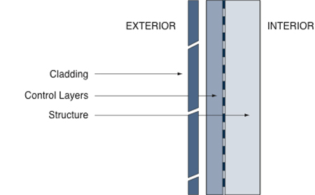
Figure 1. The "Perfect Wall" is comprised of cladding (rainwater control layer), control layers (heat, air and moisture) and structure (dead and live load control system). The interior finish and inboard integration of services is entirely optional.
In the case of below grade walls, the same arrangement applies, except the cladding is replaced by a bulk water control layer (drainage medium, mat, or membrane), which may also serve as a capillary break and thermal insulation. Alternatively, separate materials may address each of the required control functions. In all cases, this arrangement of cladding, control layers, and structure maintains a controlled thermal environment for the structure thereby reducing stresses, and promoting thermal energy storage for improved passive survivability.
The "perfect roof" is simply the "perfect wall" rotated 90 degrees such that the ballast and filter fabric serve the role of cladding. Control layers for heat, air, and moisture reside over top of the roof structure.

Figure 2. Protected membrane roofs (a.k.a. inverted roofs) observe building science principles for the ideal arrangement of building enclosure materials. By situating critical control layers under the ballast and filter fabric (cladding) these are protected from ultraviolet degradation and mechanical damage to extend the service life.
Slabs-on-grade follow the same building science principles as the "perfect wall" except that the external environment is soil instead of the atmosphere. It should be recognized that for foundations and slab-on-grade floors, moisture management considerations extend outward to include the surrounding landscape, water features, parking areas, etc.
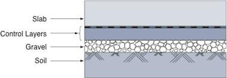
Figure 3. Slabs-on-grade are simply upside down roofs. The control layers reside immediately below the slab structure and the gravel (granular layer) serves as a capillary break and drainage layer that may be vented to the outside in order to manage any soil gas.
By adhering to this fundamental arrangement of materials and control functions, much of the enclosure design process is simplified and better performance is more practically and economically achieved. It must be recognized other arrangements are technically possible, but they are almost always sub-optimal in terms of performance, often unreliable and much less durable. The most forgiving enclosure assemblies conform to the cladding/control layers/structure model and provide redundancy for critical control functions. This underlying logic extends to all of the enclosure details and assembly transitions.
Hierarchy of Control Measures
There is an emerging discussion about what priorities should be given to control measures or functions that constitute the control layers when designing building enclosures. Heat, air, and moisture must all be managed, but is there a more efficient way to address these in the design process? At present, it is generally acknowledged that moisture management takes priority because it influences the durability of the enclosure and its susceptibility to deterioration. By addressing the measures needed to effectively manage moisture, it is often the case that measures for managing air and heat flow will be largely resolved. For example, the amount of insulation may be determined by climate, energy efficiency requirements, and economy, but the type and position of the insulation should be governed by moisture management principles. Moisture management is privileged in building enclosure design because it ultimately determines durability and to a large degree aesthetics, especially where rainwater staining of the facade is improperly managed.v Energy efficiency and thermal comfort are considerations that may be appropriately addressed after basic control functions have been adequately addressed. In most cases, these additional performance requirements will be satisfied when control functions for heat, air, and moisture have been achieved.
Control of Bulk Water
The control of bulk water in building enclosure predominantly involves rain control theory, although in some cold regions, snow accumulations and wind-driven snow present special challenges. Below-grade building enclosures (basements, crawlspaces, and slabs-on-grade) must manage precipitation that percolates through the soil as well as fluctuations in the local water table. For a simple building typology like housing, the basic strategies for managing bulk water are depicted in Figure 4.
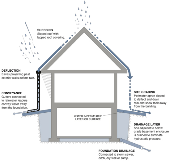
Figure 4. The simple recipe for managing bulk water is to shed it from the roof and away from the building. Projections above walls, such as extended eaves, help deflect rain and minimize the amount striking the wall surfaces. Foundations are provided with a drainage system to remove percolating water that cannot be managed by the site grading. Put simply, get as much water away from the building enclosure as possible, and provide effective drainage for any remaining moisture that may penetrate and/or accumulate.
Guidelines on the design of basements to effectively manage moisture have been developed and are available online.vi Best practices for site drainage have also been published to assist designers.vii The remainder of this resource page is devoted to exterior wall enclosures as they represent the most expensive building enclosure assembly, define the appearance of the facade, and often are the cause of costly and unsightly moisture problems.
Selecting Appropriate Wall Typologies
Looking at fundamental strategies for moisture management in exterior wall enclosures, the designer must select an appropriate typology suited to the climatic zone and precipitation exposure. (Refer to Climate, Exposure, Occupancy and Building Energy Profile in WBDG resource page Building Enclosure Design Principles and Strategies.
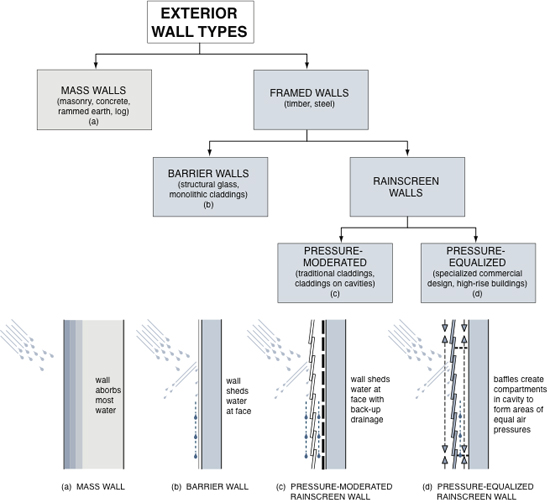
Figure 5. The typology for exterior walls based on moisture management strategies reveals four basic types. The mass wall and barrier wall do not provide acceptable performance by contemporary standards, leaving the pressure-moderated and pressure-equalized rainscreen types as being the only practical and effective alternatives from a building science perspective.
Observing the 4–Ds
Selection of a suitable wall type corresponding to precipitation exposure is a necessary but insufficient condition for adequate moisture management. The designer should attempt to observe the 4–Ds:
- Deflection—keeping as much precipitation off the exterior wall enclosure as practically possible;
- Drainage—draining away any water that does strike and penetrate the cladding;
- Drying—providing sufficient ventilation to evaporate residual moisture and arranging materials for gradual drying by diffusion; and
- Durability—selecting materials that can withstand periodic wetting without deterioration over the service life of the enclosure.
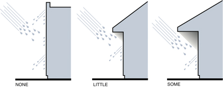
Figure 6. The profile of a building, including factors such as roof slope and eaves overhang, determines how much rain is deflected from the enclosure. In some climatic locations, wind-driven rain is so severe that the enclosure typology is much more significant than the building profile.
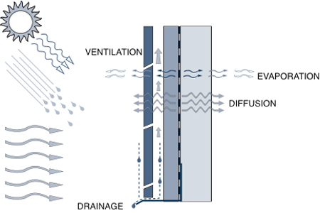
Figure 7. The various mechanisms involved in drying are dependent on the selection and arrangement of materials in the enclosure assembly as well as the climate. In some climate zones, drying potential by evaporation and ventilation is very low, at certain times negligible. This means positive drainage is critical along a drainage plane that is an effective water resistive barrier./p>
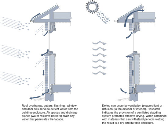
Figure 8. A typical residential enclosure depicts how the 4–Ds may be deployed. An important heuristic to observe is ensuring that it is easier for the water to get out than for it to get in—otherwise it will accumulate. Deflection, drainage, and drying are becoming increasingly important as materials become less robust because they are often thinner and less durable than their traditional counterparts.
Drainage Planes (Water Resistive Barriers)
Contemporary building science has always advocated pressure-moderated and pressure-equalized rainscreens as the most effective wall enclosure typologies for acceptable rainwater control. Over the past several decades, a great deal of research and development has gone into materials comprising the drainage plane (a.k.a. the water resistive barrier, or WRB). These water-repelling materials (sheathing paper, house wrap, sheet/roll membrane, trowel-applied mastic coating, foam insulation, coated structural sheathing, etc.) are located on the backside of the drainage space behind the cladding, to form a drainage plane. They are interfaced and/or interconnected with flashings, window/door openings, penetrations, and transitions across the building enclosure to effectively drain away to the exterior any water that penetrates the cladding.
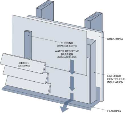
Figure 9. Wood-frame construction serves as a useful enclosure technology to demonstrate the principles of water resistive barriers. The water resistive barrier may serve as the air barrier, in which case it should be fully structurally supported to adequately resist wind pressures. The drainage cavity is compartmentalized in pressure-equalized rainscreen walls, whereas in pressure-moderated rainscreen walls, it is usually left open top and bottom to enable ventilation drying.
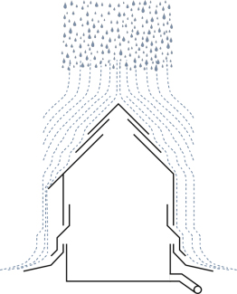
Figure 10. Flashing and shingling are based on the concepts of layering and overlap. This is a proven approach to shedding water and is highly effective at transitions between materials and assemblies, and changes in the angle or geometry of drainage cavities and planes.
It is difficult to manage rainwater without flashing because most buildings have transitions between materials, assemblies, and components that represent either discontinuities and/or changes of the geometry in the water-resistive barrier and drainage space. Flashing bridges these transitions and accommodates building movements due to settlement, shifting, and dimensional changes (expansion, contraction, swelling, shrinkage).
Most flashing design is based on successful precedents that have evolved over time. The minimum requirements for flashings have found their way into building codes and are a useful guide to designers. The number of layers of flashing and the overlap between the layers is also based on past experience. There are time and cost implications associated with the number of layers and overlap between layers that may be appreciated by considering cedar shake and shingle requirements found in many residential building codes. Figure 11 outlines the fundamental parameters and building physics involved in arriving at an acceptable overlap between shingles and shakes. Before the mechanization of shake and shingle production, generous overlaps translated into a lot more time and labor, both fabricating the shakes and shingles, and then installing them. It was soon realized that first putting down a lapped water resistive barrier, such as tar paper, provided a redundancy against rainwater penetration. In practical terms, it meant the overlap between shakes and shingles did not have to account for the most extreme of weather events since on the few occasions when rain penetration occurred, the water-resistive barrier would drain it away. Most importantly, it meant that only a single layer of shingles was required in combination with a water-resistive barrier. This logic may be extended to today's enclosure assembly design.
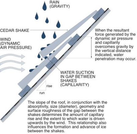
Figure 11. The rules of thumb and prescriptive requirements in building codes for the minimum overlap of cedar shakes and shingles were based on trial and error over centuries. Modern building science would rely on the first principles of physics to determine an effective overlap reinforced by laboratory and/or on-situ testing. It is important to recognize that sufficient overlap is needed to prevent water from migrating beyond the inner layer of shakes or shingles.
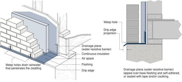
Figure 12. Base flashing that is made from durable materials like metal and is properly integrated with the water resistive barrier is critical to long term moisture management in rainscreen cladding assemblies.
While much of flashing design is based on past precedents and local experience, relatively recent research indicates that certain parameters are critical to acceptable water shedding.viii ix x The most recent laboratory testing has shown that:
Whether or not the edge of the drip edge was hemmed had the greatest impact on the shedding of water from the surface of the wall. This impact was greater for the thick 12 gauge drip edge than for the thinner 20 gauge drip edge because the larger radius at the hem fold allowed water to wrap around and drip down the wall face.
The larger 1.8 inch (45 mm) drip edge overhang had greater measured water shedding capability when compared to the 0.8 inch (20 mm) overhang in every test but one.
Adding a 45° kickout also increased the percentage of water shed from the drip edge compared to the 90° vertical drip edge.
Failing to observe these guidelines often results in water wrapping around the flashing drip edge and wetting of the cladding immediately beneath the flashing. When caulking is applied underneath the drip edge, the projection must be measured from the outer edge of the caulking bead. Facade staining and deterioration beneath improperly detailed flashing drip edges is a common but easily avoidable occurrence.
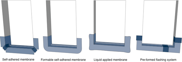
Figure 13. Pan flashing around window sills may be provided by a variety of means. The traditional pre-formed metal pan flashing is the least accommodating of dimensional variations, but is extremely rugged and durable. No matter the choice, the idea is to anticipate the inevitable water leakage within window assemblies and convey this moisture away from the enclosure while protecting the wall beneath the window from water damage.
Despite our long experience with flashing design, moving away from traditional facades and seeking more innovative facade profiles may require testing of full-scale mock-ups to ensure acceptable water shedding. It is not only how to best keep the water out, but how the shedding of water may impact the staining of facades that needs to be carefully considered.
Joint Design
Joints in cladding are inevitable and are a necessary aspect of rainscreen claddings. In some cases, joints are sealed with caulking and detailing of the joint width and geometry must take into consideration the modulus of elasticity of the caulking material so that it can accommodate movement from expansion and contraction of the joint. For open joints, it is critical to analyze the various moisture penetration mechanisms at play, and devise joints that both satisfy the aesthetic style of cladding while providing acceptable performance.
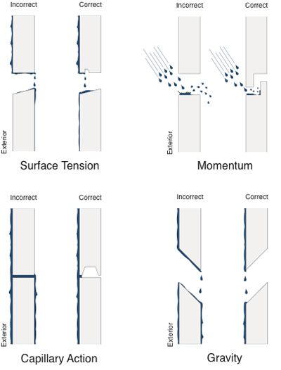
Figure 14. The design of joints between panels, sheets or board stock used for cladding in rainscreen wall assemblies is an important consideration. While the drainage cavity may have the capacity to convey water penetration away to the exterior, the material forming the cladding may become very wet, compromising its appearance and durability. In climate zones with freezing rain events, ice formation may induce stresses and deform the cladding.
Control of Capillary Water
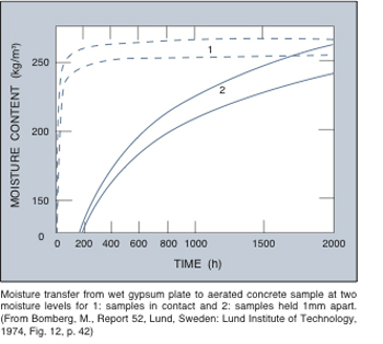
Figure 15. An airspace or gap is an effective capillary break as indicated above. A 1 mm gap between a wet gypsum plate and an aerated concrete sample retards moisture transfer by over 1500 hours compared to samples that are directly in contact. In practical terms, a gap of 1/4 to 1/2 inch between wood and saturated concrete, for example, effectively eliminates moisture migration by capillarity.
Water can migrate through hygroscopic (hydrophilic) materials driven by capillary suction into the pores of the material. Wood, brick, concrete, and numerous natural fiber products are examples of hydrophilic (water loving) materials which absorb water and transport it against the force of gravity due to capillarity. Glass, plastic and steel are hydrophobic materials which do not absorb water, however, in some configurations, these materials will exhibit capillarity if they contain capillaries (e.g., glass fiber insulation, steel wool, plastic foam sponges, etc.).
There are essentially two approaches to dealing with capillary water. The first is to apply a membrane or layer of hydrophobic material which prevents capillarity by virtue of the absence of capillaries. Dampproofing materials for below-grade foundation walls are examples of this approach. The second approach is to introduce a layer of material that contains sufficiently large voids to limit the capillary rise. The use of a layer of coarse, granular material, such as crushed stone, beneath a floor slab resting on grade, is a common example of providing a capillary break for bulk water between the capillaries in the soil, and the capillaries in the concrete. Dampproofing beneath the slab, or the use of a highly impermeable concrete (4,000 psi or better) is required to control the migration of water vapor.
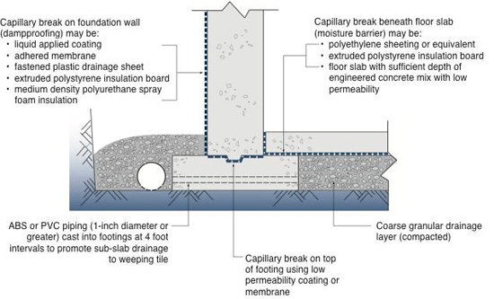
Figure 16. Dampproofing of below-grade enclosures is a form of capillary break. It should not be confused with waterproofing, which must resist hydrostatic water pressure. There are many products now available that serve as the capillary break and also provide drainage. Similar to above-grade enclosures, redundancy of critical control functions is recommended, especially in basements that are intended to be habitable.
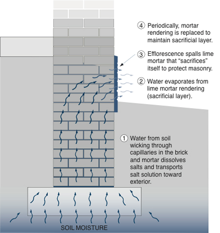
Figure 17. For existing buildings that were not provided with effective capillary water control measures, a sacrificial layer of mortar parging as shown above will preserve the integrity of the masonry foundation wall. This approach is entirely avoidable in new construction with proper capillary water management.
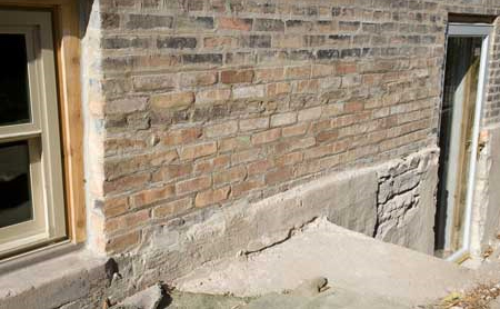
Figure 18. When dealing with existing buildings, it is important to retain the sacrificial parging layer and to repair and/or replace it if necessary. Removal of the parging will cause deterioration of the masonry beneath. Source: Marcus de la Fleur
In summary, the control of water migration through capillaries within or between building materials relies on the following strategies:
Provision of a capillary break in the form of a water impermeable material such as applied coatings, plastic films, metal sheets or any other material with low vapor and bulk water permeability.
Provision of a gap, air space or material with sufficiently large voids to prevent the capillary rise of bulk water.
The first line of defense against capillary water is the management of water by techniques such as deflection and drainage. This may not eliminate the presence of capillary water sources, but reduce their duration and intensity within manageable thresholds.
Control of Water Vapor (Diffusion and Air Leakage)
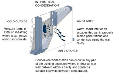
Figure 19. In cold climate zones, polyethylene sheeting is often used in residential construction to provide both an air and vapor barrier on exterior wall enclosures. This approach has proven highly effective in Canada's R-2000 energy efficient housing program since the 1980s, where mandatory airtightness testing was performed. But in many U.S. climate zones, this approach is not advisable as the polyethylene impedes the drying of wall assemblies. Even when the climate is forgiving, attention to other air leakage paths must be observed if there is a critical building enclosure surface that is below the dewpoint temperature as shown above. Continuity of the air barrier is especially critical when a single material acts as the air leakage control layer. The addition of exterior continuous insulation can reduce interstitial condensation potential and provide a degree of forgiveness to imperfections in air barrier systems.
Water vapor is everywhere in the atmosphere, both inside and outside of the building enclosure. By itself in the vapor state, it is generally harmless, and often desirable for humidification of the air. If not controlled by ventilation, it can reach excessive levels in rooms such as kitchens and bathrooms, and facilities such as swimming pools.
Water vapor is present in the atmosphere and most soils, and represents a relatively constant source of moisture which must be controlled. The physical mechanism of vapor diffusion is driven by a difference in vapor pressure across a building separator. Because vapor pressure differences are quite modest, especially when compared to air pressure differences (typically Pa versus kPa), the rate of moisture migration by vapor diffusion is lower than that generated by air leakage. But in cold climates, the vapor pressure gradient from inside to outside is sustained over the entire heating season, hence while the intensity of this phenomenon is low, the duration is very long. As a result, large quantities of water vapor can diffuse into building enclosure assemblies, accumulate and cause damage.
Water vapor is not only transported by vapor diffusion, but also by air leakage. When warm, moist air inside a conditioned building leaks through unintentional openings in the building enclosure, there is a potential for interstitial condensation to occur during periods of cold outdoor temperatures. In cold climates, the duration of this risk is over most of the heating season. Air leakage induced by indoor to outdoor pressure differences across the building enclosure can transport significant amounts of moisture, some or all of which may condense on cold surfaces within the building enclosure assembly. In severe cases, moisture accumulation may lead to damage or failure of materials, and under all circumstances, the loss of energy due to the leakage of conditioned air from the building can prove expensive.
Due to the inconsistency in the quality of materials and workmanship that is normally associated with building construction, a designer may have to accept that air leakage will occur, and deal with the realities of an imperfect air barrier. When air leakage is unavoidable, and the potential for condensation within the building enclosure is high, the most practical means of reducing the risk of interstitial condensation is to keep the air-permeable portion of an enclosure assembly above the dewpoint temperature of the air (the temperature at which the water vapor will condense and form bulk water).xi This is commonly achieved by applying a thermal protection layer (air impermeable insulation or air permeable insulation with a separate air barrier membrane) that keeps the assembly warm enough during cold conditions to avoid condensation. The conditioned interior air which migrates into the enclosure assembly is generally not harmful as long as the water remains in vapor form, and ideally the continuity of vapor flow from inside to outside is sustained. Depending on the climatic zone, it is advisable to ensure drying can occur in one or both directions out of the cavity.
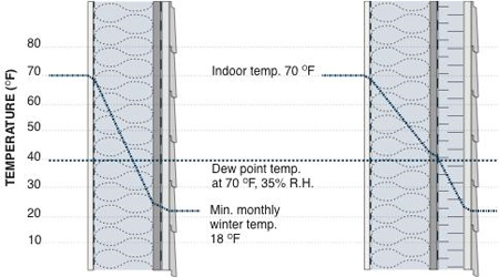
Figure 20. The simple addition of exterior insulation outboard of an insulated cavity significantly reduces interstitial condensation potential in framed wall assemblies during the heating season. If all of the cavity insulation is replaced with exterior insulation, the risk of condensation is effectively eliminated. During the cooling season, exterior insulation which has low air and vapor permeability (e.g., extruded polystyrene) resists inward air leakage and vapor drives of warm, moist air that could condense on the inboard face of the insulated cavity.
In hot climates, the direction of moisture migration is usually reversed most of the time. Warm, humid outdoor air leaking into the enclosure presents a problem if it contacts inwardly situated materials which have been cooled by mechanical air conditioning or passive ventilation and shading/cooling. Highly vapor permeable interior finishes and/or exterior insulation materials with low air and vapor permeability are recommended measures for controlling moisture migration due to air leakage in hot climates.
Designers of building enclosures must carefully consider the need for redundancy and multi-functionality of constituent materials. In some cases, a single material may control multiple mechanisms, such as in the case of extruded polystyrene which controls heat and vapor flows, and with proper attention to details and the sealing of joints, can also contribute to air leakage control. In other cases, several materials in an assembly may share the control functions. It should be recognized that the quality and consistency of materials and workmanship associated with single materials which resist multiple mechanisms, is far more critical than is the case for assemblies which are comprised of materials which share control functions and hence provide redundancy (higher factor of safety).
The residential wall assembly depicted in Figure 21 was widely used in cold Canadian climate zones and has performed acceptably. However, it is not an advisable choice in many warmer, mixed and coastal climate zones due to its low drying potential. Despite the best design detailing and execution of workmanship confirmed by airtightness testing and thermography, buildings become more porous as they age due to occupant behavior (wear and tear, damage), normal deterioration and lack of maintenance. Enclosures that cannot tolerate flaws should be avoided in practice, and climate should predicate their attributes.
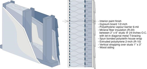
Figure 21. The wall assembly depicted here is commonly selected in cold climate zones and found to perform very well, largely due to the redundancy of control functions and use of multi-functional materials. The polyethylene sheeting on the warm side of the insulated assembly serves as a vapor barrier and an air barrier if it is properly sealed at penetrations. The house wrap installed between the wood studs and the exterior insulating sheathing also contributes to airtightness and reduces air movement in the air-permeable batt insulation. The plastic foam insulation board reduces the potential for interstitial condensation, minimizes thermal bridging and serves as the drainage plane when the joints are sealed or taped. It also contributes to the overall airtightness of the wall enclosure assembly and guards against inboard vapor drives during the cooling season. Forgiving enclosures comprise redundant critical control functions and multi-functional materials to achieve economical buildability.
In summary, the control of moisture migration due to diffusion and air leakage involves the following strategies:
Provision of a vapor control layer(s) that suitably retards diffusion within the moisture management threshold of the enclosure assembly. Typically, the vapor control layer will be situated on the inboard side of insulated cavities in cold climates, and on the outboard side of insulated cavities in hot climates. In mixed climates, the vapor permeability and location of the vapor control layer must be selected to minimize wetting potential while maximizing drying potential, often with the help of hygrothermal analysis tools.
Provision of a continuous, structurally sound air barrier system which is properly sealed at all penetrations.
Location of the air barrier, if it is also a vapor barrier (low vapor permeability), on the warm side of insulated assemblies in cold climates (or in a location within the assembly that exhibits low condensation potential on a seasonal basis). Alternatively, use a vapor permeable air barrier.
Where air leakage control may be difficult to achieve or maintain, then the designer must carefully select and arrange vapor control layers and thermal insulation materials to reduce condensation potential and promote drying.
Critical Details
Up to this point in devising suitable strategies for the management of bulk water, the designer will have given careful consideration to:
- Water shedding from the building and site/foundation drainage;
- Deployment of a suitable enclosure typologies that observe the cladding/control layers/structure model;
- Integration of the 4–Ds for controlling moisture from precipitation (rain control);
- Selection and arrangement of materials to minimize wetting potential, while maximizing drying potential (acceptable hygrothermal performance); and
- Provision of sufficient redundancy to account for imperfect materials and workmanship while accommodating the expected aging of control layer materials and possibly escalating severities of extreme weather phenomena due to climate change over the useful life of the building.
The final step in the design process, and often the most challenging, is to develop critical details at transitions between materials and assemblies. For example, the wall-roof and wall-window transitions must maintain the continuity of the control layers, to name a few of the many interfaces that must be properly resolved. One of the benefits of the integrated design process for buildings is the ability to bring architects, engineers, manufacturers and contractors together to help develop and review critical details. People do not inhabit drawings and specifications; they live inside what has been constructed. Without proper follow through in terms of mock ups, field reviews, and building enclosure commissioning, the best of strategies may not to be properly executed, and as a result, the building may fail to achieve its expected level of performance.
Moisture Management Strategies Synopsis
The control of moisture migration is a fundamental requirement for well performing, durable building enclosures. Contemporary control measures utilize technologies that range in origin from previous millennia to the present day, and provide designers with a broad choice of options. Irrespective of the option(s) selected, the fundamental physical phenomena that drive moisture migration must be fully understood and addressed by any control measure.
Selecting appropriate moisture management strategies is key to successful building enclosure design. Factors such as the climate zone and precipitation exposure will determine candidate typologies that are suitable to the exterior environment to which the enclosure will be exposed throughout its useful service life. Selection of a suitable typology is insufficient by itself, and the choice of materials according to their physical properties and their arrangement, particularly those comprising control layers, must be made exercising care and considering bulk water, capillary water and water vapor migration mechanisms. Finally, details that integrate all of these elements into a complete building enclosure system must be developed, tested and reviewed in the field to ensure acceptable performance.
Additional Resources
Organizations
The The Air Barrier Association of America provides information related to the science and construction of air barriers.
Many of the current issues related to building enclosure construction for moisture control are discussed by the Building Sciences Corporation. The following online publications are recommended for reference and review:
- BSD-030 Rain Control Theory by Straube, John. 2010-08-06.
- BSD-013 Rain Control in Buildings by Straube, John. 2007-10-16 (updated 2011-08-23)
- BSD-104 Understanding Air Barriers by Lstiburek, Joseph. October 20, 2006.
- BSD-105 Understanding Drainage Planes by Lstiburek, Joseph. October 24, 2006.
- BSD-106 Understanding Vapor Barriers by Lstiburek, Joseph. October 24, 2006.
- BSI-011 Capillarity—Small Sacrifices by Lstiburek, Joseph. January 27, 2009.
- BSI-049 Confusion About Diffusion by Lstiburek, Joseph. May 9, 2011.
- Info-301 Drainage Plane/Water Resistive Barrier by Building Science Corporation. May 13, 2009.
- Info-302 Pan Flashing for Exterior Wall Openings by Building Science Corporation. May 13, 2009.
- Info-303 Common Flashing Details by Building Science Corporation. May 13, 2009.
Publications
Staining of Facades
- Predicting environmental performance of facade geometry by el-Shimi, Mahmoud A. Master's thesis, Concordia University, Montreal, Canada, 1979.
- Prevention of Premature Staining in New Buildings by Parnam, Phil. Taylor and Francis. 1997.
- Rainwater runoff from building facades: a review by Blocken, B., D. Derome and J. Carmeliet. Building and Environment, Volume 60, February 2013, Pages 339-361 Building and Environment, October 17, 2012.
- Staining of Facades by Chew, Michael Y.L. and Tan Phay Ping. World Scientific Publishing Co., January 2004.
Metal Flashing Performance and Water Resistive Barriers
- The Importance of Integrating Flashing and the Water Resistive Barrier in the Exterior Wall Systems of Residential BuildingsDownload Journal of ASTM.pdf by Dorin, Leonard. Journal of ASTM International, Vol. 3, No. 5, March 2006.
- Summary of Research on Water Resistive BarriersDownload 63677.pdf. Research Highlight, Technical Series 04-124, Canada Mortgage and Housing Corporation, August 2004.
Pressure Equalized Rainscreens
- ASTM E 241-77, Recommended Practices for Increasing Durability of Building Constructions Against Water-Induced Damage. Philadephia, PA: American Society for Testing and Materials, 1977.
- Pressure Equalization in Rainscreen Wall SystemsDownload ctu-n17_eng.pdf M.Z. Rousseau, G.F. Poirier and W.C. Brown. Institute for Research in Construction, Construction Technology Update No. 17, July 1998.
- Pressure Moderation and Rain Penetration ControlDownload Pressure_Moderation_Seminar.pdf by John Straube. Ontario Building Envelope Council, Proc. of Pressure Equalized Rainscreens: Design and Performance, International Plaza Hotel, Toronto, Canada, Nov. 21, 2001.
- Rain Control and Design Strategies by John Straube and Eric Burnett. Journal of Building Physics, July 1999, vol. 23, no. 1, pp. 41-56.
- Rain Penetration Control: Applying Current Knowledge by Canada Mortgage and Housing Corporation, Ottawa. 1999.
- The Difference Between a Vapour Barrier and an Air BarrierDownload 54_e.pdf by Quirouette, R.L. Building Practice Note No. 54, Division of Building Research, National Research Council Canada, July 1985.
- Ventilated rainscreen cladding: A study of the ventilation drying process by Falk, Jörgen and Kenneth Sandin. Building and Environment 60, pgs. 173-184, 2013.
- Ventilated rainscreen cladding: Measurements of cavity air velocities, estimation of air change rates and evaluation of driving forces by Falk, Jörgen and Kenneth Sandin. Building and Environment 59, pgs. 164-176, 2013.
References
i. Moisture Control in Buildings: The Key Factor in Mold Prevention, ASTM MNL18-2nd, October 2009.
ii. Makepeace, C. and Dennis B. PERSIST—Pressure Equalized Rainscreen Insulated Structure Technique—Design Approach. Thermal Envelopes VII / Performance of Air Barrier Systems - Practices. pp. 767-772, 1998.
iv. Lstiburek, J. The Perfect Wall. Building Science Insight 001, Building Science Corporation, Revised 2010.
v. Blocken, B., D. Derome and J. Carmeliet. Rainwater runoff from building facades: a review. Building and Environment, Volume 60, February 2013, Pages 339-361 Building and Environment (October 17, 2012).
vi. Swinton, M.C. and T. Kesik. Performance Guidelines for Basement Envelope Systems and Materials. Institute for Research in Construction, National Research Council Canada, Ottawa, October 2005.
vii. Swinton, M. and T.J. Kesik. Site Grading and Drainage to Achieve High Performance BasementsDownload ctu-n69_eng.pdf. Construction Technology Update No. 69. Institute for Research in Construction, National Research Council Canada, June 2008.
viii. Saneinejad, Saba and Hitesh Doshi. Testing Of Metal Flashing For Water-Shedding Effectiveness. RCI Inc., Interface Technical Journal, Raleigh, NC, September 2006. Available at rci-online.org/publications/tech-library/
ix. Maleki, Afarin, Ramani Ramakrishnan and Hitesh Doshi. Impact of Sealant on the Water Shedding Performance of Metal FlashingDownload THESTUDYOFIMPACTOFCAULKINGONTHEWATERSHEDDINGPERFORMANCEOFMETALFLASHING-AFARINMALEKI.pdf. 11th Canadian Conference on Building Science and Technology, Banff, Alberta, 2007.
x. Smegal, J., Lukachko, A., Straube, J. and Trainor, T. Quantitatively Evaluating the Effectiveness of Different Drip Edge Profiles. Proceedings of the 14th Canadian Conference on Building Science and Technology, Toronto, Ontario Canada, October 28-30, 2014, pp. 89-99.
xi. Straube, J. BSD-163: Controlling Cold-Weather Condensation Using Insulation. Building Science Corporation, 2011.


