Overview
Within This Page
Runways are the primary operating surface at airfields and essential to fixed-wing aircraft operations. Fixed-wing runways are built in a variety of lengths, widths, and pavement types depending on a large number of factors, including:
- Aircraft Type (Operating Characteristics, Wingspan, Weight)
- Mission
- Number of Operations
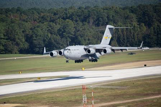
C-17 touchdown on runway
Source: Defense Visual Information Distribution Service
The primary reference describing requirements for DoD Fixed Wing Runways is Chapter 3 of UFC 3-260-01, Airfield and Heliport Planning and Design. Other special use runways (Landing Zones, STOVL Facilities and UAS runways) are defined in Chapters 7, 8 and 9 of the UFC.
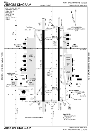
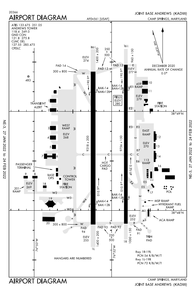
Typical airport diagram
(View enlarged diagram)
Source: Federal Aviation Administration
Each DoD Service classifies fixed-wing runways into two primary categories—Class A or Class B—depending primarily on the type(s) of aircraft using the runway. That classification drives many required construction features of the runway, including length, width, transverse slopes, and longitudinal grades. It should be noted that civilian runways are classified by a very different system, defined in Federal Aviation Administration Advisory Circular 150/5300-13, Airport Design, with a classification system based on the critical aircraft's wingspan and landing approach speed.
Fixed-wing runways are usually constructed with a rigid pavement surface (Portland cement concrete) or flexible pavement surface (asphalt cement concrete), but in special cases may be surfaced with compacted soil, aggregates, or segmented aluminum mats, depending on the mission requirements.
Taxiways are used by aircraft to enter and exit a runway and transit to an aircraft parking position. Taxiways connect directly to runways, most often at the runway ends.
In addition to the runway pavement surface, there are many ground surface areas immediately surrounding the runway that improve safety for the operating aircraft by limiting the risk of damage should an aircraft accidentally depart from the runway surface.
Not only must objects be restricted from close proximity to the runway surface, the airspace surrounding a runway must also be protected from development that encroaches on the airspace needed for safe aircraft operations. The protected areas are defined by what are known as "imaginary surfaces." These are generally planar or conical surfaces in the air, defined by a length, width, and slope up to a specified elevation.
Runway Design
There are many different factors that impact runway design and are dependent on many different data inputs. All components should be determined early in the planning process to avoid unexpected challenges or constraints later in the design development.
Runway Heading
Runways are oriented to provide the best conditions for an aircraft on takeoff and landing. An aircraft moving directly into the wind has the highest airspeed across the wing, thereby increasing lift, and the least sideways forces on the aircraft. Therefore, the ideal orientation of the runway (often referred to as the heading) is determined by analyzing historical wind data (10 years or more) at a location. Wind heading and speed data is graphically displayed on a Wind Rose, and this tool can be used to determine a runway heading that provides the greatest percentage of time with favorable winds for aircraft operations. The objective is to find a heading that allows operations more than 95% of the time with a crosswind less than 19.5 km/hr (10.5 knot). When a single runway cannot provide this coverage, then a crosswind runway may be required. UFC 3-260-01, Appendix B, Section 4 explains this process in detail.
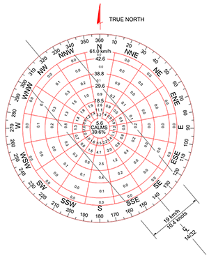
Windrose used for Runway Heading Analysis
Source: UFC 3-260-01, Appendix B, Section 4
In addition to prevailing winds, other factors may affect the selection of a runway heading, including terrain, obstructions, restricted airspace, noise effects, built-up areas, or operational procedures.
Runway Length
Each service determines the required runway length using their own procedures that generally take into account the mission aircraft performance requirements, altitude, and typical temperature range.
-
Air Force: For both Class A and B runways, the length will be determined by the Major Command responsible for the airfield.
-
Army: The Class A runway length requirement is listed in UFC 3-260-01, Table 3-3, but for Class B Runways, runway length is determined by the using aircraft operator, in conjunction with HQ Department of the Army.
-
Navy and Marine Corps: UFC 2-000-05N describes the process for determining runway length to accommodate the critical aircraft in both takeoff and landing operations under stated load and environmental conditions. Minimum lengths by aircraft type are listed in Table 11110-1; then adjusted for altitude, temperature, and effective gradient with a safety factor applied to the result.
Runway Width
For the DoD, the runway width is dependent on the type of aircraft planned to use the airfield. Table 3-1 in UFC 3-260-01 classifies aircraft into Class A or B. Then Table 3-2 defines the required runway width for each class. There are some exceptions to the standard widths, as defined in Item 2. Runways for Bombers like the B-52 are 300-ft wide, and some training runways for small aircraft are only 75-ft wide. Special-use runways (Landing Zones, Short Takeoff and Vertical Landing (STOVL) facilities, and Unmanned Aircraft Systems (UAS) runways have their own requirements, defined in UFC 3-260-01, Chapters 7, 8 and 9.)
Clear Zones and Accident Potential Zones
Clear Zones are areas on the ground at the ends of runways that have a high potential for accidents. Other uses of the clear zone are restricted to be compatible with aircraft operations. Each DoD service defines clear zones differently, so UFC 3-260-01, Table 3-5 should be carefully considered to provide the appropriate dimensions. Clear Zones should be owned and controlled by the agency to prevent incompatible development within the areas.
Accident Potential Zones (APZs) are land-use control areas, mandated by the Air Installation Compatibility Use Zones (AICUZ) program, and intended to promote only compatible development in areas under the approach and departure surfaces for fixed-wing runways. The APZs usually stretch beyond the base property boundaries, so coordination with the local communities is essential to avoid building high population development in these areas where an aircraft accident is more likely to occur.
Imaginary Surfaces and Obstructions
The area above the ground surrounding a runway that must be kept clear of objects that might damage an aircraft operating around the airfield (approach, departure or circling) is defined by Imaginary Surfaces (planar or conical surfaces in the airspace). An object that projects above an imaginary surface is an obstruction. Typical terminology for imaginary surfaces includes:
- Primary surface
- Approach-departure surface
- Inner horizontal surface
- Conical surface
- Outer horizontal surface
- Transitional surface
Each of these surfaces is defined in UFC 3-260-01, Chapter 3.
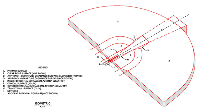
Isometric view of airspace around Fixed-Wing Runway (View enlarged)
Source: UFC 3-260-01, Chapter 3
Grades
There are strict requirements for the slope or grade of the runway pavement surfaces and ground surfaces surrounding the runway. These surfaces are dependent on the performance requirements of the aircraft (Class A or B) and to promote good drainage as well as aircraft safety in the event that an aircraft accidentally departs from the runway surface. UFC 3-260-01, Chapter 3 defines the requirements for the grades of the following items:
- Longitudinal Grades and Rate of Grade Change for Runways, Shoulders, Overruns and Lateral Clearance Zone
- Transverse Slopes for Runway, Shoulders, Overruns and Lateral Clearance Zone
- Longitudinal and Transverse Grades in the Clear Zone
Pavement Thickness Design
Runway pavements for military airfields are designed following the procedures described in UFC 3-260-02, Pavement Design for Airfields. Typically, runways are constructed with a flexible pavement structure (asphaltic concrete pavement) or rigid pavement structure (Portland cement concrete).
For pavement thickness design, each Service divides an airfield and the runway into different types of traffic areas, (e.g., Type A, Type C, Primary, or Secondary). The traffic type then correlates to different traffic patterns (aircraft load, number of repetitions, and the typical "wander" of the aircraft traffic). When traffic is combined with the subgrade strength, the required pavement thickness can be determined.
Pavement Markings
To improve the visibility of runways during both day and night, standard markings are painted on the pavement surface. There are three primary runway marking schemes—Visual, Non-Precision Instrument, and Precision Instrument—with progressively more markings. Runway markings are white (as compared to yellow markings on taxiways) and include embedded glass beads to provide reflectivity. At each end, the runway heading number is painted, and when there are one or more parallel runways, a left (L), right (R) or center (C) designation is also applied.
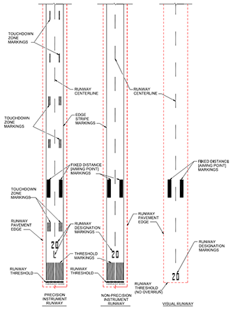
Marking schemes for Fixed-Wing Runways
(View enlarged)
Source: UFC 3260-04, Chapter 5
UFC 3-260-04, Airfield and Heliport Marking, fully defines pavement marking requirements for Army and Air Force fixed-wing runways. Navy and Marine Corps requirements are defined in NAVAIR 51-50AAA-2, General Requirements for Shorebased Airfield Marking and Lighting. Each Service's requirements very closely match the Federal Aviation Administration runway marking requirements.
Runway Lighting and Signs
For low visibility and night operations on runways, lights and signs are used to provide visibility of the runway to pilots when operating on the ground and in the air. The most basic fixed-wing runway lighting system consists of edge lights, threshold lights and end lights, used to outline the lateral and longitudinal limits of the usable surface of the runway. These lights are required for visual flight rules (VFR) night operations and for all categories of instrument operations. In some cases where minimal visibility operational capability is needed, the runway perimeter lighting is augmented with touchdown zone and centerline lighting in-pavement light fixtures.
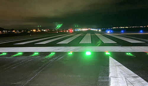
Runway threshold lighting and markings
Source: Crawford, Murphy & Tilly, Inc.
Approach light systems provide visual guidance to pilots aligning their aircraft with the runway and attempting final corrections before landing at night or during low visibility. There are several different types of approach lighting systems (MALSR, SSALR, ALSF-1, ALSF-2), each with a different number of lights and different configurations.
UFC 3-535-01, Visual Air Navigation Facilities, fully defines lighting and signage requirements for Army and Air Force fixed-wing runways. Navy and Marine Corps requirements are defined in NAVAIR 51-50AAA-2, General Requirements for Shorebased Airfield Marking and Lighting. Each Service's requirements very closely match the Federal Aviation Administration runway lighting and signage requirements.
Electronic Navigational Aids (NAVAIDs)
Some aircraft are equipped with electronic devices that can use radio signals to provide direction, distance, and glide slope data to help the pilot guide the aircraft to the runway. These systems are called NAVAIDs and consist of a wide variety of antennas installed in various configurations surrounding the runway. For example, an Instrument Landing System (ILS) consists of a Localizer antenna and Glide Slope antenna. The Localizer transmits a radio signal down the centerline of the runway into the approach zone, and the pilot can use the signal to align on the runway. The Glide Slope transmits a radio signal upwards from the runway surface at the correct approach angle the aircraft should follow to touchdown at the appropriate location on the runway surface. Many different types of NAVAID systems have been developed over the years and are deployed at DoD installations. UFC 4-141-10, Airfield Operations Support Facilities describes the different types of NAVAIDs, including installation requirements for each system.
Relevant Codes and Standards
Federal Aviation Administration
Naval Air Systems Command
Unified Facility Criteria
- UFC 2-000-05N Facility Planning for Navy and Marine Corps Shore Installations
- UFC 3-260-01 Airfield and Heliport Planning and Design
- UFC 3-260-02 Pavement Design for Airfields
- UFC 3-260-04 Airfield and Heliport Marking
- UFC 3-535-01 Visual Air Navigation Facilities
- UFC 4-141-10 Airfield Operations Support Facilities