Overview
Within This Page
The primary Navy aviation facilities this page will focus on are: aircraft maintenance hangars, paint hangars, jet engine test cells, and air traffic control.
Navy aviation facility design is typically approached with the intent of maximizing the functional uses for the squadrons as well as providing for future mission change. Facilities are generally standardized in size to allow for carrier-based aircraft to be accommodated in one size of facility and for larger marine patrol aircraft to be housed in another facility type.
Classification
Aircraft Maintenance Hangars
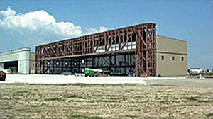
Aircraft Maintenance Hangar with header truss roof framing system
The basic function of an aircraft maintenance hangar is to provide flexible space that accommodates change in base loading and to provide optimum use of the flight line for aircraft access. The single most important factor in determining the hangar design and layout is the hangar structural roof-framing system. The most valuable real estate at an airfield is the flight line. So, the roof framing system selected for the hangar design must optimize access to the flight line.
Recent Design Criteria Enhancements
Until recently, the Navy has mandated the use of the cantilever roof framing system. This system minimizes flight line columns that restrict aircraft movement. The cantilever system also lends itself to future expansion by removal of an end wall and extending the hangar down the flight line. However, a cantilever system is an inefficient method for supporting loads, is prone to larger deflections, and is more difficult to erect. The cantilever designer needs to carefully consider the effect of erection sequencing, actual versus predicted loads, and environmental conditions during the fabrication and erection.
The header truss system can span modules or the entire flight line face of the building resting on supports at the front corners of the hangar. The remaining walls of the hangar are conventionally framed. Lateral support is provided through the walls and the truss supports. Intermediate support to the truss is provided in the plane of the roof through a diaphragm, dedicated horizontal truss bracing, or a combination of the two.
The structural efficiency and stiffness decrease exponentially as the span of the truss increases. Increasing the depth of the truss can offset this. Practical limits of transporting fabricated hardware, erecting the assembled truss and the lateral bracing system limit the truss depth to approximately 7.5 meters. A header truss virtually precludes the use of an expansion joint along the centerline of the hangar bay and extends the practical thermal expansion limit. The header truss system also requires the flight line frontage be dedicated to structural supports. Construction documents for a header truss must clearly indicate the camber requirements. The designer must carefully consider the influence that temperature and erection rigging will have on completing the final connections as well as the final camber.
The Navy has recently agreed to allow the hangar framing system to be based on an economical decision in unison with the long-range planning of the airfield. The Navy is continually searching and assessing innovative ways to improve the quality of the workplace for the sailors, operators, and maintenance personnel by taking the best of today and building a better aviation facility for tomorrow.
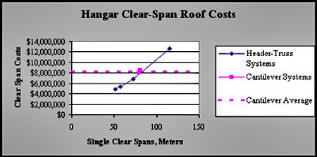
Graph of Economic Comparison of Header Truss versus Cantilever Truss
Paint Hangars
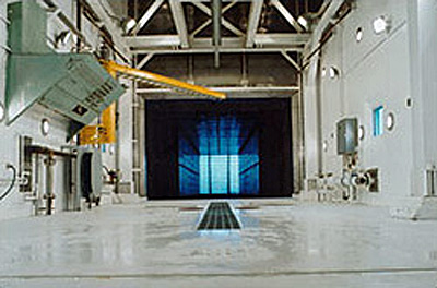
Paint hangers are considered spray areas instead of spray booths. The primary design criteria of interest for Navy paint hangars is design airflow. The Navy has carefully evaluated ventilation requirements for paint hangars and follows the guidance prescribed for industrial ventilation as outlined in Industrial Ventilation: A Manual of Recommended Practice for Design by the American Conference of Government Industrial Hygienists (ACGIH) that allows designers to use a flow range between 50 and 75 cfm/ft². The Navy recommends 50 cfm/ft² because hangars are very large, tall, deep work areas that dilute paint fumes very quickly. The Navy's paint hangar ventilation goals are to: prevent explosion or fire; protect the employee from hazardous exposure; to provide a quality paint product; and to ensure good housekeeping of the paint bay. In a 1997 OSHA letter to the Navy, OSHA "considered these hangers to be spray areas since painting was incidental to the specific area that is being treated." There is no specific OSHA standard that pertains to ventilation rates other than maintaining the concentration of the vapors and mists in the exhaust stream of the ventilation system to not more than 25 percent of the lower flammable limit.
There is no existing Industrial Hygienist exposure-monitoring data throughout the Navy indicate for corrosion control hangers that indicate worker overexposure. Regardless of airflow (50-100CFM or more), Navy designers anticipate that respiratory protection would still be required as the primary containment means as opposed to the building ventilation system.
Jet Engine Test Cells
Jet Engine Test Cells provide an enclosed facility for out-of-airframe testing of Navy/Marine Corps jet engines that is intended to provide repeatable results with a standard day correction factor of one (1) as the goal-the test results for indoors and outdoors would be equal. Enclosed cells also reduce noise emission to within OSHA standards. The NAVFAC standard aircraft engine test facilities are complex to design, build, and maintain because they are extensions of Navy/Marine Corps aircraft systems rather than routine buildings. Test cell facilities are designed with special air intakes and exhaust to ensure engine performance consistency and to suppress noise to OSHA acceptable levels. Reduction of heat and vibration from engine exhaust are additional design concerns. NAVAIR aircraft controls and instrumentation are integrated into test cell design to verify satisfactory engine performance prior to returning engine to fleet inventory.
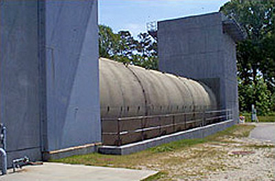
Navy's traditional out-of-airframe jet engine test cell lined with acoustical pillows and perforated stainless steel inner panels
Representative Example
The NAVFAC Criteria Office and Atlantic Division Naval Facilities Engineering Command recently sponsored a new design innovation for jet engine test cells in response to acquisition cost reduction and constructability concerns. The new design features a square exhaust augmenter instead of the elliptical configuration normally employed. The new design provided a $500,000 savings in the initial construction cost as well as an anticipated savings of $100,000 in reduced maintenance costs. The jet engine test cell facility's aero/thermodynamic performance is essential to consistent engine test results and preventing accelerated building deterioration. The engine manufacturer requires verification of the engine repairs and reassembly by repeatable, prescribed engine test results. Minor airflow variations can significantly distort engine performance or prematurely fail building components. The Navy has long been recognized as the world's leader in aircraft engine test system design. The new design has correlated with the previous standard for acoustical, aero/thermodynamic, and general engine performance testing. Advanced mathematical modeling at the Naval Facilities Engineering Service Center (NFESC) and physical scale modeling at The Ohio State University Aeronautical Research Center were conducted prior to changing the Navy's standard design. The Architect/Engineer of record worked with a team of Navy experts to identify and resolve problems from concept through final acceptance. The construction contractor from Seely, Texas partnered with the design team to build the prototype facility at Naval Air Station (NAS) Oceana, Virginia Beach, Virginia. Naval Air Warfare Center Lakehurst and NFESC jet engine test cell experts consulted with the Navy's design/construction team throughout the process to ensure the original test cell performance criteria was preserved in the next generation version.
The Architect/Engineer of record encountered significant engineering challenges throughout the design and construction of the square augmenter test cell. The Architect/Engineer of record verified the new test cell aero/thermal behaved consistent with previous Navy Round Exhaust Augmenter Cells (a large exhaust pipe). The most important criteria for engine performance was to ensure that the primary inlet velocity was laminar and limited to 50 feet per second in the mathematical, 1/12th physical scale, and full-scale model testing. The Architect/Engineer of record faced demanding structural challenges as well to verify the new augmenter connections would survive the Navy's jet engine testing harsh environment. In addition to high acoustical and jet blast pressures, the new augmenter had to withstand 500-degree temperature changes for 10,000 cycles. All connections had to be designed to ensure that the augmenter acoustical panels returned to the original position after experiencing the cyclic 500-degree temperature change.
The Navy modeled and built two square augmenter panels at the Engineering Services Center to demonstrate performance of the proposed design connection details for the new precast concrete to stainless steel acoustical liner sheets in the augmenter. The demonstration section verified: a) that stainless steel panel alignment was maintained after 20 cycles of thermal loading, and b) that heat transfer was not detrimental to the lightweight precast concrete at the connection points. After simulating an F-110 engine in full military after burner at NFESC test lab in Port Hueneme, California, the Navy found the inner stainless steel panel face reached 500 degrees Fahrenheit above ambient with only 150 degrees transferred to the precast concrete inner surface. Panel alignment from continuous expansion and contraction and heat transfer concerns were mitigated from the design.
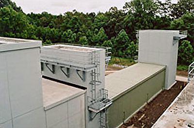
Precast lightweight concrete for the outer square shell of the augmenter lined with acoustical pillows and perforated stainless steel inner panels
For the preliminary square augmenter aero/thermal evaluation (August, 2001) three engines (TF 30, F-110, and the F404) tested within performance parameters per the test director; the test cell exhibited primary inlet velocity airflow problems as documented by the F-110 data for Engine Run Room profile at maximum AB power. Resolution of this airflow problem was carefully evaluated by a team of experts. From the conceptual design all the way through the prototype facility construction, the common thread that ensured a successful product delivery was the partnering and teamwork to attack a problem and develop a solution that was best for the end user.
The construction phase went better than any other test cell constructed by the Navy prior to that time. Partnering and teamwork throughout the construction phase was instrumental in resolving complex issues. Final acceptance was facilitated by the formation of an expert aero/thermal team to identify concerns and resolve issues quickly. All team members were committed to delivering a quality product, on time, and within budget.
Specialized knowledge and expertise were required to design, construct, and accept the NAS Oceana test cell facilities. The Architect/Engineer, the Construction contractor, NFESC, Naval Air Systems Command (NAVAIR), and Atlantic Division Naval Facility Engineering Command (LANTDIV) jointly provided technical support for the NAS Oceana square augmenter test cell. Good communications and constant involvement eliminated conflicting guidance to the contractor. The customer is very pleased with the end product he received as demonstrated by his production testing of 36 F-404 engines within the first 2 months since final acceptance.
The design was a multi-disciplined approach to facility engineering with a heavy emphasis on the aero/thermal, acoustical, and structural performance of the test cell exhaust augmenter. The Navy's square augmenter design is a lightweight reinforced precast concrete tees with acoustical stainless steel panel treatment that spans between the precast concrete webs. The augmenter structural frame is a combination of a rigid steel frame and precast concrete tee that had special temperature isolation points at the connection points to prevent the temperature absorbed by the steel inner liner surface from being transferred to the concrete that would be susceptible to spalling. The augmenter absorbs and cools the engine's hot exhaust gases requiring components to expand and contract over a 500 degrees Fahrenheit design temperature change and return to its original configuration without misalignments. The 500 degrees Fahrenheit design temperature change was the governing structural loading condition for design. The augmenter connections were one of the most challenging issues confronting the design team. The contractor/designer team partner ultimately produced the optimum solution. The stainless steel design panels had to be free to expand and contract in all directions yet return to their original position and remain stable through engine testing. The team ultimately agreed upon a snug tight pin approximately at the panel's center of mass with slots at other locations on the panel to provide for a temperature expansion and contraction. The precast outer shell has the same tight tolerances for fabrication and erection; however the temperature change was limited to 150 degrees Fahrenheit above ambient.
Augmenter stainless steel square cross section
The design team learned from the mathematical and physical scale modeling that every component within the test cell interrelated to the performance of the rest of the cell. The exhaust stack was modified by replacing the exhaust ramp with turning vanes and the exhaust stack cross section area was reduced to save construction costs and more evenly distribute the air flow. The secondary stack that is used to mix and cool the engine exhaust gases was also slightly reduced in cross section.
The construction of the innovative design presented its share of problems. The exhaust stack structural steel failed during the first engine test. The designer used steel struts to support the turning vanes that were fixed on both ends. The traditional Navy exhaust ramp provides for a fixed condition at the base and a roller at the strut top to allow up to 4" of thermal movement. The struts buckled laterally. A field fix provided a heavy angled bracket with slotted connections to provide for expansion due to over a 700-degree temperature change when the F-14 engine was in full military after burners. The exhaust stack is lined with acoustical panels that protect the concrete from the high exhaust temperatures. These panels are designed to expand and contract in any direction. The inner skin is a perforated stainless steel sheet used to encapsulate thermal and acoustical insulation. Normally, the 18-gauge stainless steel material takes the high acoustical loadings because the perforations instantly equalize the pressure. Unfortunately, the acoustical panels are held in place with a friction connection with carefully controlled anchor tension. Due to the high temperature change, the panels need to be free to expand and contract. The installer apparently overtightened the bolts and created a binding condition when the panels tried to expand resulting in a buckling of the panel skin.
Air Traffic Control Towers
The Navy's structural design of Air Traffic Control (ATC) Tower Facilities is based on ASCE 7 Minimum Design Loads for Buildings and Other Structures for dead, live, and wind loading, UFC 1-200-01 General Building Requirements, UFC 3-310-04 Seismic Design for Buildings and FEMA 368. The Navy has recently designed and constructed three towers in the Norfolk/Virginia Beach area where wind controlled the design lateral loads by a significant amount (33.3% above horizontal base shear from seismic loading). NAS Whidbey Island is currently going through final design and NAS Brunswick is in the design request for proposal stage. NAS Whidbey Island and NAS Brunswick have treated their tower designs as an essential facility in accordance with FEMA 368.
The three east coast towers use a concrete shear wall box system and were designed under the old P-355 (TM 5-809-10) criteria. The NAS Whidbey Island tower will be the Navy's first air traffic control tower designed under the performance based criteria required by UFCs 1-200-01 and 3-310-04 and FEMA 368. The Whidbey Island design team decided to use steel braced frame. The design occurrence selected for NAS Whidbey Island was a once in 2500-year occurrence.
The Force Protection design requirements for an Air Traffic Control Facility shall be according to the UFC 4-010-01 DoD Minimum Antiterrorism Standards for Buildings. Generally, the number of air traffic controllers is less than 10 people and the facility is rated as un-inhabited. For major activity at ATC facilities, the air traffic controllers number around 15, invoking the requirement for a progressive collapse analysis.
The Navy feels the selection of the seismic performance objectives should be carefully based on whether the structure is mission essential, not because ACTs appear in the essential facilities category in the seismic use group. The owner, architect, and structural engineer of record should carefully review the performance objectives as described in UFCs 1-200-01 and 3-310-04 before final design of the tower is initiated. The Navy believes emergency and alternate communication systems, plans for quickly diverting air traffic to alternate fields, and the presence of temporary towers can all be considered a redundant facility to, perhaps, assign the facility a life-safety occupancy versus immediate occupancy.
The Navy is currently evaluating its policy and criteria for Air Traffic Control Towers in an effort to clarify ambiguities that might exist between the UFCs 1-200-01 and 3-310-04 and FEMA 368. The Navy expects to issue guidance on static versus dynamic analysis by September 30, 2004, particularly for air traffic control facilities falling in seismic design category D, E, or F for either the FEMA or UFCs 1-200-01 and 3-310-04 analysis.
Relevant Codes and Standards
- ICC IBC International Building Code or other state mandated building code
- UFC 4-211-01N Aircraft Maintenance Hangars: Type I, Type II and Type III
- NFPA 70: National Electric Code®
- NFPA 409: Standard on Aircraft Hangars


