Introduction
Within This Page
Microturbines are a relatively new distributed generation technology being used for stationary energy generation applications. They are a type of combustion turbine that produces both heat and electricity on a relatively small scale.
Microturbines offer several potential advantages compared to other technologies for small-scale power generation, including: a small number of moving parts, compact size, lightweight, greater efficiency, lower emissions, lower electricity costs, and opportunities to utilize waste fuels. Waste heat recovery can also be used with these systems to achieve efficiencies greater than 80%.
Because of their small size, relatively low capital costs, expected low operations and maintenance costs, and automatic electronic control, microturbines are expected to capture a significant share of the distributed generation market. In addition, microturbines offer an efficient and clean solution to direct mechanical drive markets such as compression and air-conditioning.
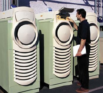
Microturbines work like jet engines but produce electricity instead of thrust. Photo Credit: Capstone Turbine Corp.
Description
A. What is a Microturbine?
| Microturbine Overview | |
|---|---|
| Commercially Available | Yes (Limited) |
| Size Range | 25-500 kW |
| Fuel | Natural gas, hydrogen, propane, diesel |
| Efficiency | 20-30% (Recuperated) |
| Environmental | Low (<9–50 ppm) NOx |
| Other Features | Cogeneration (50–80°C water) |
| Commercial Status | Small volume production, commercial prototypes now. |
(Courtesy of California Distributed Energy Resources Guide on Microturbines)
Microturbines are small combustion turbines approximately the size of a refrigerator with outputs of 25 kW to 500 kW. They evolved from automotive and truck turbochargers, auxiliary power units (APUs) for airplanes, and small jet engines. Most microturbines are comprised of a compressor, combustor, turbine, alternator, recuperator (a device that captures waste heat to improve the efficiency of the compressor stage), and generator. The figure below illustrates how a microturbine works.
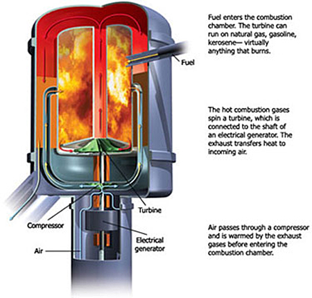
How a microturbine works. Courtesy of slimfilms.com
B. Types of Microturbines
Microturbines are classified by the physical arrangement of the component parts: single shaft or two-shaft, simple cycle, or recuperated, inter-cooled, and reheat. The machines generally rotate over 40,000 revolutions per minute. The bearing selection—oil or air—is dependent on usage. A single shaft microturbine with high rotating speeds of 90,000 to 120,000 revolutions per minute is the more common design, as it is simpler and less expensive to build. Conversely, the split shaft is necessary for machine drive applications, which does not require an inverter to change the frequency of the AC power.
Microturbine generators can also be divided into two general classes:
Unrecuperated (or simple cycle) microturbines—In a simple cycle, or unrecuperated, turbine, compressed air is mixed with fuel and burned under constant pressure conditions. The resulting hot gas is allowed to expand through a turbine to perform work. Simple cycle microturbines have lower efficiencies at around 15%, but also lower capital costs, higher reliability, and more heat available for cogeneration applications than recuperated units.
Recuperated microturbines—Recuperated units use a sheet-metal heat exchanger that recovers some of the heat from an exhaust stream and transfers it to the incoming air stream, boosting the temperature of the air stream supplied to the combustor. Further exhaust heat recovery can be used in a cogeneration configuration. The figures below illustrate a recuperated microturbine system. The fuel-energy-to-electrical-conversion efficiencies are in the range of 20 to 30%. In addition, recuperated units can produce 30 to 40% fuel savings from preheating.
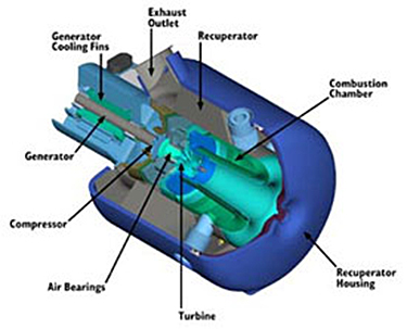
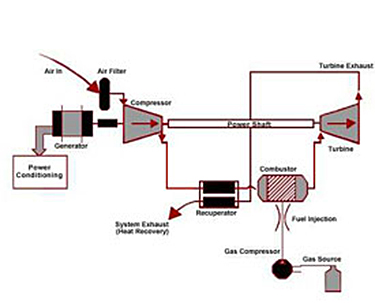
Recuperated microturbine Photo Credit: Capstone
View enlarged diagram Courtesy of EPRI
Cogeneration is an option in many cases as a microturbine is located at the point-of-power utilization. The combined thermal electrical efficiency of microturbines in such cogeneration applications can reach as high as 85% depending on the heat process requirements.
| Microturbine Efficiency | |
|---|---|
| Configuration | Efficiency |
| Unrecuperated | 15% |
| Recuperated | 20–30% |
| With Heat Recovery | Up to 85% |
(Courtesy of California Distributed Energy Resources Guide on Microturbines)
Advanced materials, such as ceramics and thermal barrier coatings, are some of the key enabling technologies to further improve microturbines. Efficiency gains can be achieved with materials like ceramics, which allow a significant increase in engine operating temperature.
C. Characteristics of Microturbines
Some of the primary applications for microturbines include:
- Distributed generation—stand-alone, on-site applications remote from power grids
- Quality power and reliability—reduced frequency variations, voltage transients, surges, dips, or other disruptions
- Stand-by power—used in the event of an outage, as a back-up to the electric grid
- Peak shaving—the use of microturbines during times when electric use and demand charges are high
- Boost power—boost localized generation capacity and on more remote grids
- Low-cost energy—the use of microturbines as base load or primary power that is less expensive to produce locally than it is to purchase from the electric utility
- Combined heat and power (cogeneration)—increases the efficiency of on-site power generation by using the waste heat for existing thermal process.
Microturbines offer many potential advantages for distributed power generation. Selected strengths and weaknesses of microturbine technology are listed in the following table from the California Distributed Energy Resources Guide on Microturbines.
| Microturbines | |
|---|---|
| Strengths | Weaknesses |
| Small number of moving parts | Low fuel to electricity efficiencies |
| Compact size | Loss of power output and efficiency with higher ambient temperatures and elevation |
| Lightweight | |
| Good efficiencies in cogeneration | |
| Low emissions | |
| Can utilize waste fuels | |
| Long maintenance intervals | |
| No vibrations | |
| Less noise than reciprocating engines | |
| Strengthens energy security | |
Accessible: N/A
- Improves sightlines and views with off-the-grid systems, which eliminate the need for overhead power lines
Cost-Effective: (See Section F: Economics of Microturbines)
- Enables cost savings by reducing the peak demand at a facility, therefore lowering demand charges
- Provides better power reliability and quality, especially for those in areas where brownouts, surges, etc. are common or utility power is less dependable
- Provides power to remote applications where traditional transmission and distribution lines are not an option such as construction sites and offshore facilities
- Can be an alternative to diesel generators for on-site power for mission critical functions (e.g., communications centers)
- Possesses combined heat and power capabilities
- Reduces upstream overload of transmission lines
- Optimizes utilization of existing grid assets—including potential to free up transmission assets for increased wheeling capacity
- Improves grid reliability
- Facilitates faster permitting than transmission line upgrades
- Can be located on sites with space limitations for the production of power
- Provides high-quality power for sensitive applications
- Responds faster to new power demands—as capacity additions can be made more quickly
- Facilitates less capital tied up in unproductive assets—as the modular nature of microturbines means capacity additions and reductions can be made in small increments, closely matched with demand, instead of constructing central power plants sized to meet estimated future (rather than current) demand
- Stand-by power decreases downtime, enabling employees to resume working
- Produces less noise than reciprocating engines
- Strengthens energy security
- Stand-by power provides quick recovery after an event
- Produces the lowest emission of any noncatalyzed fossil fuel combustion system
- Has a small footprint, minimizing site disturbance
- Reduces or defers infrastructure (line and substation) upgrades
- For recuperated microturbine, possesses higher energy conversion efficiencies than central generation
- Enables more effective energy and load management
D. Economics of Microturbines
Microturbine capital costs range from $700–$1,100/kW. These costs include all hardware, associated manuals, software, and initial training. Adding heat recovery increases the cost by $75–$350/kW. Installation costs vary significantly by location but generally add 30-50% to the total installed cost.
Microturbine manufacturers are targeting a future cost below $650/kW. This appears to be feasible if the market expands and sales volumes increase.
With fewer moving parts, microturbine vendors hope the units can provide higher reliability than conventional reciprocating generating technologies. Manufacturers expect that initial units will require more unexpected visits, but as the products mature, a once-a-year maintenance schedule should suffice. Most manufacturers are targeting maintenance intervals of 5,000-8,000 hours.
Maintenance costs for microturbine units are still based on forecasts with minimal real-life situations. Estimates range from $0.005–$0.016 per kWh, which would be comparable to that for small reciprocating engine systems.
| Microturbine Cost | |
|---|---|
| Capital Cost | $700–$1,100/kW |
| O&M Cost | $0.005-0.016/kW |
| Maintenance Interval | 5,000-8,000 hrs |
(Courtesy of California Distributed Energy Resources Guide on Microturbines)
Application
Microturbines can be used for stand-by power, power quality and reliability, peak shaving, and cogeneration applications. In addition, because microturbines are being developed to utilize a variety of fuels, they are being used for resource recovery and landfill gas applications. Microturbines are well suited for small commercial building establishments such as: restaurants, hotels/motels, small offices, retail stores, and many others.
The variety of energy consumers that are already using microturbines is large and growing fast. For example:
Landfill gas-fired microturbines installed at the Jamacha Landfill in Spring Valley, California supply power on-site and back to the grid. More
A McDonald's restaurant in Chicago, Illinois, gets most of its electricity from a natural-gas-powered microturbine, cutting $1,500 off its total monthly power bill.
A Parallon 75 microturbine generator power system at The Energy Efficient McDonald's (TEEM) in Bensenville, Illinois, is able to power the entire store, including lighting, cooking equipment, and HVAC. Photo Credit: Energy User News
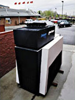
A textile mill in Lawrence, Massachusetts, ensures continuous operation by getting its power from microturbines.
The Chesapeake Building on the University of Maryland campus, College Park, Maryland has a cooling, heating, and power (CHP) system consisting of microturbines, chiller, and stack that uses waste heat to cool and heat the building, significantly increasing system efficiency.
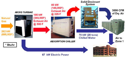
Chesapeake Building CHP system, University of Maryland—College Park, MD
The development of microturbine technology for transportation applications is also in progress. Automotive companies are interested in microturbines as a lightweight and efficient fossil-fuel-based energy source for hybrid electric vehicles, especially buses.
Other ongoing developments to improve microturbine design, lower costs, and increase performance in order to produce a competitive distributed generation product include heat recovery/cogeneration, fuel flexibility, and hybrid systems (e.g., fuel cell/microturbine, flywheel/microturbine).
Relevant Codes and Standards
- Executive Order 13693, "Planning for Federal Sustainability in the Next Decade"
- National Energy PolicyDownload National-Energy-Policy.pdf . Report of the National Energy Policy Development Group, May 2001.
- IEEE Standards Association IEEE 1547a - Standard for Interconnecting Distributed Resources with Electric Power Systems, Amendment 1
Additional Resources
State and Federal Agencies
Associations and Organizations
- California Communities for Advanced Distributed Energy Resources (CADER)—Serves as an information clearinghouse on efficient technologies and infrastructure systems that improve the quality, reliability and security of community energy supplies, while reducing energy costs and environmental impacts associated with power generation.
- CHP Association—An association that brings together diverse market interests to promote the growth of clean, efficient CHP in the United States. Its mission is to create a regulatory, institutional, and market environment that fosters the use of clean, efficient CHP as a major source of electric power and thermal energy in the U.S. (Formerly U.S. Clean Heat and Power Association (USCHPA))
- World Alliance for Decentralized Energy (WADE)—Launched by a group of major companies and national industry associations to accelerate the development of high efficiency cogeneration and decentralized energy (DE) systems which will deliver substantial economic and environmental benefits worldwide.
Manufacturers
There are more than twenty companies worldwide that are involved in the development and commercialization of microturbines for distributed generation applications. Below are links for five of the leading microturbine manufacturers.
- Bowman Power Systems—A U.K. company that develops 80-kW microturbine power generation systems for DER and mobile power applications.
- Calnetix Technologies—A premier manufacturer of microturbines for use in distributed generation, combined heat and power (CHP), biogas and offshore applications.
- Capstone Turbine Corporation—Based in Chatsworth, CA, Capstone is a leader in the commercialization of low-emission, high-reliability microturbine power generators. The company offers 30-kW and 60-kW systems for DER applications.
- Ansaldo Turbec— In late 2012 Ansaldo Energia acquired Turbec. The company offers a 100-kW microturbine power generator for commercial DER applications.


