Introduction
Within This Page
Just months after occupying their new, multimillion-dollar municipal building, employees of a Florida county began complaining of chronic sinus problems, allergy attacks, headaches, and asthma—classic signs of sick building syndrome and building-related illness. The architects, engineers, and microbiologists tasked with finding the cause of these symptoms identified a problem that is becoming widespread nationwide—severe fungal contamination of the building.
The mold was the direct result of excess moisture in the building, which was caused by a combination of rainwater leaks and a heating, ventilating, and air-conditioning (HVAC) system that pulled moist outside air into the building during the hours when the cooling system had cycled off. Once the HVAC system became infected with mold, it dispersed spores throughout the building. So, only a few years after opening its doors, the building underwent a major overhaul.
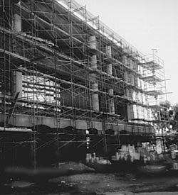
Figure 1. Although brand new, this municipal building was evacuated shortly after it opened because occupants were reporting health complaints. Mold and moisture were the culprits, and in the end, the problem will require more than $20 million to repair.
The building's exterior was removed to help correct the problems that allowed rainwater to invade the building envelope (Figure 1). The roof and the HVAC system were also extensively modified. Ultimately, repairs and other associated costs exceeded $20 million.
Unfortunately, the problem faced by this Florida county is not an isolated one. Rainwater leaks occur in every climate, and in this case study, the leaks alone would probably have led to significant microbial contamination and building evacuation. But both architects and engineers must understand the interaction between the building envelope and the HVAC system to manage moisture intrusion in buildings.
Description
To avoid the types of problems seen at the Florida municipal building, engineers and architects must work together to manage moisture. First, the building designer must understand the basic causes of moisture intrusion into buildings:
Rainwater intrusion. Moisture present in building materials and on the site during construction can be a source of problems. Significant amounts of moisture can also result from water leaks within building systems or through the building envelope. In both hot, humid and temperate climates, rainwater leaks are a major source of building moisture and fungal growth problems.
Infiltration of outside moisture-laden air. Infiltrated humid air, whether introduced by wind or through the HVAC system, can cause condensation on interior surfaces, including inside building cavities. Condensation and high relative humidity levels are important factors in creating an environment conducive to mold growth and are the primary problems in hot, humid climates. The issue of infiltration caused by negative pressure of the building created by HVAC systems is detailed in HVAC Design and Construction in Humid Climates.
Internally generated moisture. After construction, occupant activities and routine housekeeping procedures can generate additional moisture, contributing to the mold problem. Normally, if no other significant sources exist, well-designed and properly operating HVAC systems can adequately remove this moisture.
Vapor diffusion through the building envelope. Differential vapor pressure, which can cause water vapor to diffuse through the building envelope, is a less significant cause of moisture problems in buildings in hit humid climates. However, it can be a significant moisture movement mechanism, particularly in cold climates, and especially as it relates to wall system vapor retarder construction.
In hot, humid climates, the interrelationship between the building envelope and the building HVAC system is especially critical. Many moisture and mold-related problems in humid climates are often misdiagnosed as either exclusively envelope- or HVAC-related, because the complex relationship that exists between both systems is not always clearly understood.
Moisture-related problems can be avoided if the building envelope does the following:
- Adequately retards moisture or air movement into the building
- Allows any accumulated moisture to either drain to the exterior or evaporate
In hot, humid climates, the air barrier and vapor retarder in the building envelope must be adequate to control air and moisture flow through the wall system. This means that any air barrier or vapor retarder placed within the wall system must have the proper air resistance or moisture permeability and must be installed at the correct location within the walls. The presence of multiple vapor retarders within a wall system is a common problem, because many designers do not recognize many construction materials as effective barriers. For example, plywood is a relatively low-permeability material that can function as a vapor retarder.
The point where cool surfaces meet warm, moist air is where condensation and excess moisture can occur. If moisture-laden outside air is retarded before it meets the first cool surface inside the building envelope (often called the "first plane of condensation"), then few problems will result. If this moisture is allowed to further enter a wall system, it will condense. Then, moisture and mold growth problems can be a real threat. If the cool surfaces and moist air meet within the building space, then moisture problems can occur throughout the building, resulting in widespread mold odors and complaints from occupants. Thus, the building envelope plays a vital role in minimizing uncontrolled moisture and air movement into a building and in preventing moisture entrapment within the wall system.
Confusion still exists within the design community about several critical issues related to envelope performance. These issues include the integrity requirements of air barriers, weather barriers, and vapor retarders; the way all three barriers/retarders can be incorporated into one membrane; the location of these features within the building envelope; the effects of using multiple vapor retarders; and even the need for air barriers and vapor retarders in every facility.
This confusion about design, construction, and operational practices between humid and non-humid climates accounts for many moisture and mold growth problems. ASHRAE Fundamentals (2009) cautions that different climates present different problems, and buildings should be designed and operated accordingly.
Application
During the design phase, especially early in design, many low or no-cost decisions can be made regarding the HVAC and envelope systems that will have a significant impact on moisture management. Figure 2 summarizes the moisture control considerations typically associated with the schematic design phase. Although the responsibility for addressing the considerations can be divided according to architectural and mechanical functions, personnel in both disciplines should work together closely to prevent future problems. Effective interaction among design team members is crucial in creating a problem-free design.
Figure 2 highlights some typical design issues that must be considered by the design team during the schematic design phase and shows the relationship between the architectural and mechanical aspects of the design.
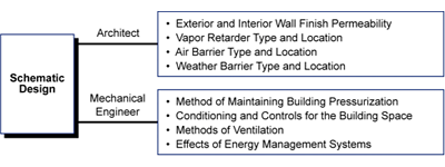
Figure 2. These issues must be considered in the schematic design phase.
While it is known that some design decisions will inevitably create a greater risk of moisture intrusion, the extent of a problem with moisture or mold is determined by other less extensive decisions made after the fundamental design choices.
Architectural Considerations
While no detailed designs are completed during the schematic design phase, decisions are made that form the basis of designs developed during the next phase (Design Development, Section 3). Available design handbooks for humid, rainy, or cold climates may not provide all the information necessary to complete comprehensive construction designs. The architectural design team, therefore, must use sound judgment in selecting the building envelope system during schematic design, including the weather and air barriers and the vapor retarder (Figure 3).
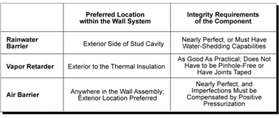
Figure 3. In hot, humid climates, the design, location, and installation of the air and weather barriers are more critical than for the vapor retarder. Note: The vapor retarder location specified above is specifically for hot, humid climates. In cold climates, the location of the retarder is to the interior side of the thermal insulation.
Because all of the possible moisture-related issues in new construction are not always immediately apparent to an architect, design issues relating to the architectural aspects of construction must be addressed by the entire design team. For example, interior finishes are often selected simply for aesthetic appeal, initial cost, or ease of maintenance. However, the permeability of the interior finish (indicated by permeance rating) can greatly affect the moisture and mold potential of a design, depending on the type of HVAC system being considered. Therefore, the mechanical engineer and the architectural design team members should all have input when selecting a wall system.
Vapor Diffusion
Vapor diffusion potential is a function of the vapor pressure differential across the building envelope (Figure 4). Hot, moist air has a higher pressure than cool, dry air. A large amount of vapor pressure results from a high moisture content. The vapor pressure at any moisture content is equal to the sum of all individual vapor molecule pressures. A large amount of water vapor creates considerable force; in fact, in some instances the pressure difference can be great enough to blister and peel paint on exterior siding as moisture in the wood or masonry is drawn out. Vapor diffuses through walls at a rate proportional to the vapor pressure difference. If one side of a wall is much drier than the other side, the vapor will diffuse faster (The Dehumidification Handbook, 1990).
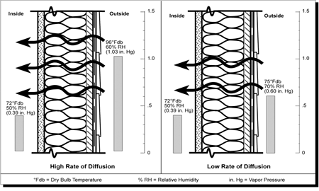
Figure 4. Vapor diffuses through a wall at a rate proportional to the vapor pressure difference across the wall.
Vapor diffusion issues tend to be greatest in cold climates, where even small amounts of internally generated moisture will condense inside cold wall cavities during winter months. In those climates, locating a vapor barrier on the interior (the warm side of the wall) is required. In hot humid climates, the vapor diffusion mechanism does not typically induce significant moisture into a building, particularly in conventionally air-conditioned commercial buildings with moderate temperature conditions. However, in buildings with colder than normal temperatures, for example, hospital operating rooms, vapor diffusion and condensation can still occur.
Air Leakage
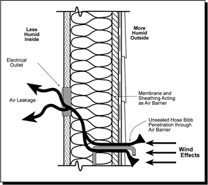
Figure 5. Air leakage into the building can be affected by typical building envelope penetrations.
No building is hermetically sealed. That is, all buildings have some degree of air leakage openings inherent in the envelope construction, and this leakage carries a certain amount of moisture with it into, or out of, the building (Figure 5). Although this leakage can typically be overcome with good positive pressurization, a tightly sealed building envelope will minimize air leakage and reduce the amount of air required by the HVAC system to achieve good pressurization. Moisture contributed by air leakage is a significant source and should be a serious concern in the design of the wall system. In fact, the design of the building envelope for minimizing air leakage is more critical than the design of the vapor barrier.
To illustrate this point, consider that the amount of moisture contributed to a building by the air that flows through a crack 1/16th inch thick by 1 foot long is just over 5 pints per day in a light breeze. In contrast, the amount of moisture contributed by vapor diffusion through a 10 foot by 50-foot painted block wall over the same period equals just under 1/3 of a pint (about 5 ounces). The most critical areas of envelope air leakage are gaps around windows and doors; joint openings at roof, ceiling, or floor lines; and perhaps the greatest contributor, the intentional installation of soffit or wall vent systems. These areas provide the most likely openings in a building envelope and are convenient pathways for air leakage and moisture intrusion into the building.
Rainwater Leakage
In addition to moisture entering the building via vapor diffusion or air leakage, moisture as rainwater can be drawn into a building by gravity, capillary action, surface tension, air pressure differentials, or wind loads. The building envelope (exterior walls and roofing) acts as the interface between the interior and exterior of buildings. To avoid moisture problems in the extreme weather conditions, building envelope design must control water from all of these factors.
Weather-related moisture includes water intrusion from rainwater and groundwater. Rainwater and groundwater intrusion most severely affect the building envelope. Rainwater rarely affects HVAC systems or building interiors to the degree required to cause widespread building moisture problems. Water concentrates around window and door penetrations, the roof line and construction joints, and the base of exterior walls.
The following forces are most commonly applied to the building envelope:
Gravity. The force of water entering by gravity is greatest on improperly sloped horizontal surfaces and vertical surfaces with penetrations. These areas must remove water from envelope surfaces through adequate sloping, correct drainage, and proper flashing.
Capillary action. This is the natural upward wicking force that can draw water from one source up into the envelope cavity. This occurs primarily at the base of exterior walls. Building components that cannot withstand a large amount of water exposure, such as plywood or gypsum board, can create environments conducive to microbial growth and/or component failure.
Surface tension. This allows water to adhere to and travel along the underside of building components such as joints and window heads. This water can be drawn into the building by gravity or unequal air pressures.
Air pressure differentials. In hot, humid climates if air pressures are lower inside the structure than outside the structure, water can be "driven" from the exterior to the interior of the building through microscopic holes in the building materials.
Wind loading. Wind loading during heavy rainstorms can force water inside the building if the envelope is not resistant to these forces. For example, window sealants and gaskets that are not properly designed to flex with the window may create air gaps that can allow water into the building.
Wall System Components
Most wall systems used in new construction are framed wall systems, poured-in-place concrete, or masonry wall systems (concrete block or brick).
Framed wall systems consist of an interior wall finish system and an exterior wall finish system, separated by an air space (or cavity). The cavity, which normally includes insulation material for added thermal resistance, provides a potential path for the movement of moisture throughout the wall areas. Storefront wall systems and exterior insulation and finish systems (EIFS) are framed construction.
A concrete or masonry wall system is constructed of a structural wall material. If internal and external finishes are applied directly to the surface of the structural wall, air movement within the wall is restricted. However, if the interior finish is applied to a furred gypsum board attached to the structural wall, a potential pathway for air movement is created.
The primary wall system components requiring special attention for moisture control (Figure 6) are listed below:
- Exterior wall finishes
- Vapor retarders
- Air infiltration and rain barriers and seals
- Insulation
- Interior wall finishes
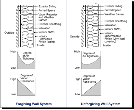
Figure 6. A "forgiving" (well-designed) wall system for hot, humid climates has a high resistance to outside air and vapor movement. The component most responsible for restricting air and water vapor movement should be located toward the exterior of the wall system. For colder climates, the high vapor resistant finishes must be on the interior side of the insulation in order to avoid condensation.
Exterior Wall Finishes
Materials commonly used as exterior finishes in construction include stucco, wood siding, concrete or masonry, brick veneer, and proprietary external finish systems that combine insulation and finish coatings (such as EIFS). In selecting the exterior finish material, the design team needs to consider the effects of moisture penetration and vapor and air migration, as well as aesthetics, to ensure consistency with the design intent. Consideration of porous materials such as concrete or masonry should include the ability of these materials to limit moisture and vapor migration into and out of the wall system, as well as their ability to act as air barriers. Often the aesthetic exterior finish of a concrete or masonry wall system is a paint or stucco type of application. These exterior finishes, as well as the structural concrete or masonry substrate, may be effective weather barriers but are ineffective vapor retarders and only partially effective air barriers.
Materials used in the construction of exterior walls are classified by their resistance to moisture movement through the material when there is a vapor pressure difference between the interior and exterior sides of the material. Three categories of vapor retarder capability are typically defined:
- Vapor impermeable: less than or equal to 0.1 perm
- Vapor semi-impermeable: less than or equal to 1 perm and greater than 0.1 perm
- Vapor semi-permeable: greater than 1 perm
Concrete block walls can have a permeance of 2 to 3 perms, whereas painted stucco finishes can have a permeance as high as 25 perms. Exterior paint systems with 1 to 3 mil dry-film thickness, such as commercial latex paints, can range from 5 to 10 perms (Figure 7). Paint systems are good examples of how requirements for temperate, cold, and hot/humid climates differ. In most parts of the country, exterior paint systems have high permeance ratings and interior paint systems have lower permeance ratings. In hot, humid climates, wall finish design requirements are just the opposite: exterior systems should have lower permeance ratings than interior paint systems.
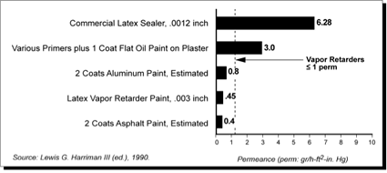
Figure 7. Many exterior paints and coatings can act as adequate vapor retarders.
Vapor Retarders
A vapor retarder is not required in all situations. The building envelope (minus a dedicated vapor retarder) may perform as an adequate barrier to vapor diffusion. Under many conditions, using an air barrier is more important than using a vapor retarder. While using a vapor retarder is not always necessary, if one is used, factors such as permeance, location, and use of multiple retarders become extremely important.
The type and location of the vapor retarder can affect moisture accumulation and mold formation considerably. For example, a wall system vapor retarder located between the thermal insulation and the building's interior could reach a temperature below the dew point (point of condensation in hot, humid climates and an exterior vapor retarder could be below the dew point in northern climates) of the outside air, allowing condensation to form on interior surfaces or in interior cavities. To avoid such problems, decisions regarding vapor retarders are best determined during the schematic design phase.
There are several types of vapor retarders (Figure 8). Rigid retarders include reinforced plastics, aluminum, and similar materials that are relatively impervious to moisture flow. They are mechanically fastened into place and may have sealed joints. Flexible vapor retarders include foil, laminated foils, treated papers, coated felts and papers, and plastic films. Joints in these materials must be sealed with another material. (Airtight joint sealing is not a requirement unless the vapor retarder is also acting as an air barrier and/or a rainwater barrier.) Some coating materials (such as epoxies) can also be classified as vapor retarders.
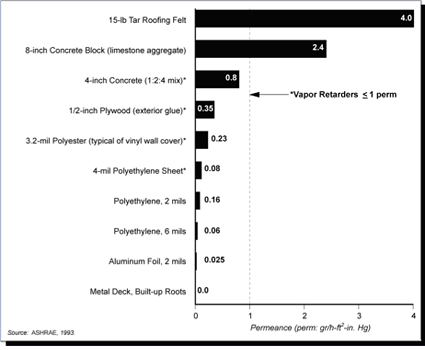
Figure 8. Vapor transmission rates among common construction materials differ dramatically.
The permeance of a material is determined by how porous the material is. Different vapor retarder materials have different permeance ratings depending on how much vapor will diffuse through it during a given period and for a given area. For example, a .002 inch-thick aluminum foil sheeting has a permeance of .025, which means it passes .025 grain (1/7,000 of a pound) per hour per square foot of area for every inch of mercury column vapor pressure difference. By contrast, an 8 inch concrete block (limestone aggregate) passes 2.4 grains per hour, a rate 90 times greater than the aluminum foil, even though the block wall is 48,000 times thicker (The Dehumidification Handbook, 1990).
Each of these vapor retarders can be used with the wall systems described previously. Typically, frame-type cavity walls include flexible vapor retarders. Designing the vapor retarder location for concrete or masonry wall systems can be more difficult than for a framed wall system. Applied coatings are particularly suited for concrete or masonry walls; applying the exterior finish system directly to the poured-in-place wall substrate is easier than including an interstitial space (or buildout) on the exterior of the wall substrate to install a vapor retarder. Moreover, the latter process may threaten the integrity of the wall. In selecting a vapor retarder for the exterior wall finish system, a vapor retarder paint may be considered.
The selected vapor retarder should have a permeance rating less than 1.0 perm. (However, in temperate regions, a vapor retarder with a very low permeance rating may create problems because the vapor diffusion mechanism will reverse directions between winter and summer months.) Although the design criteria may dictate a particular vapor retarder, or thickness thereof, the installation method can often mandate substitution. For example, a polyethylene sheet vapor retarder may meet design criteria but may not provide adequate resistance to tearing during field installation. The performance of a vapor retarder is reduced if penetrated, although avoiding all penetrations is not necessary.
Using two low-permeance finishes in a wall system, such as a polyethylene vapor retarder on the exterior and vinyl wall covering on the interior, should also be avoided. This arrangement can allow moisture to become trapped within a wall system without the ability to dry in either direction, thus promoting moisture accumulation and mold formation. Using multiple vapor retarders within a wall system can be successful only if both rainwater intrusion and outside air infiltration are virtually eliminated. Thus, achieving and continually maintaining positive building pressurization is critical in this situation.
Air Infiltration Barriers and Seals
The decision to include a dedicated air barrier in the design is typically made at during schematic design. An air barrier can play an important role in deterring infiltration from wind load or weather conditions and also can facilitate building pressurization. (Air barriers called building wraps are commonly used in northern climates for energy savings.) The proper location of the air barrier may be the same as that of the weather barrier and vapor retarder. Therefore, a well-designed combination of air/weather/vapor barrier sometimes can be economically achieved.
An air barrier in a wall system, however, should never be viewed as an adequate envelope seal to offset a depressurized interior building space and prevent internally induced infiltration. The building envelope must work with the HVAC system to establish a pressurized building. Because cavities that may exist within a wall system provide potential pathways for outside air, maintaining proper pressurization is crucial to avoiding infiltration of outside air into these spaces.
Often, the building envelope components acting together can function as an effective air barrier. ASHRAE recognizes that a single piece of properly supported plywood or gypsum board sheathing can be an adequate air barrier. However, joined pieces of sheathing often will not be as effective unless the joints are reasonably well sealed. While the effectiveness of a vapor retarder diminishes linearly as the number of penetrations increases, the effectiveness of an air barrier diminishes exponentially as the number of joints, cracks, and crevices increases. Thus, the performance of an air barrier depends on its being as penetration-free as possible.
Wood products, including sheet goods and finished boards, are less effective as air barriers if normal installation methods are used. Because these exterior finish systems tend to allow air infiltration from wind and thermal effects, an additional means of limiting air (and moisture migration) through the wall system is required. A combination air/weather barrier should be installed on the exterior sheathing substrate, particularly in a framed wall system that uses wood products.
The effectiveness of combining insulation board and an exterior finish (i.e., EIFS) as air barriers depends on the overall integrity of the composite exterior system. If joints are reasonably plumb and tight, the system will protect the building envelope from infiltrating wind and outside air. Closed-cell and nonhygroscopic (nonabsorbent) insulation board are more resistant to vapor-diffused moisture than open-cell insulation board.
Insulation
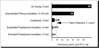
Figure 9. Some insulation types can also serve as effective vapor retarders. Special attention must be given to insulation thickness to achieve the desired permeance.
Using closed cell, nonhygroscopic insulation can help minimize the high moisture levels that can develop in wall systems. Insulation should be installed next to a vapor retarder whenever possible and should be inwardly located so that the vapor retarder does not reach the dew point during operation of the building AC system (this condition applies only to hot, humid climates and is the reverse in cold climates). Some insulation types can also be used as effective vapor retarders (Figure 9).
To avoid moisture problems, the design team must consider how direct contact with moisture-laden air affects wall structures. Thermal bridges that allow the structures to cool below the dew point of the ambient air may cause local condensation on the structural materials. For example, a metal stud framing system in a framed wall system can act as a thermal short-circuit or bridge, allowing condensation to occur on interior or exterior portions of the metal stud even though the wall may be well insulated.
Interior Wall Finishes
Interior finish selection is a critical consideration, especially in humid climate design. The contribution of the interior finish to severe moisture and mold problems in existing and new buildings is well documented. Using an impermeable interior finish without full consideration of infiltration, outdoor dew point temperatures, and the possibility of condensation at the primary vapor retarder location will often result in moisture entrapment and mold problems.
Vinyl wall covering is a commonly used interior finish and normally has a low permeance (or a very high resistance) to water vapor migration through a wall system. A problem can develop, however, in hot, humid climates when outside air infiltrates a wall cavity, contacts a cooler surface, condenses, and cannot dry. (The vinyl wall covering's high vapor retarder characteristics prevents the condensation from drying.) The condensation will degrade the finish substrate, usually gypsum board, providing an excellent growth medium for mold. Consequently, vinyl wall covering should be limited to areas where moist air is unlikely to infiltrate (that is, interior walls) or in buildings where positive building pressurization can be ensured. In cold climates the use of vinyl wall covering is not a problem and will, in fact, retard the unwanted diffusion of warm moist air into the wall cavity where condensation can occur on the exterior side of the thermal insulation.
In general, in hot, humid climates the permeance of the interior finish material should be significantly higher than the permeance of the other components in the wall system. This difference will allow moisture vapor that enters the wall system to migrate into the conditioned space, where the vapor eventually will be removed by the AC system. To ensure success, all portions of the wall system located inwardly from thermal insulation must be more permeable than components external to the thermal insulation. Again, the reverse of this condition is advised in cold climates where moisture should not be trapped inside the cavity on the exterior of the thermal insulation.
Wall Dew Point Analysis
Each major exterior wall system used in construction should be analyzed to determine all of the following:
- Where dew point will occur
- What the temperature profile will be
- Where the primary vapor retarder will be located
- How far moisture will be allowed to penetrate
(vapor pressure profile)
These concepts are discussed in the ASHRAE Handbook: Fundamentals (Chapter 27; ASHRAE, 2009). Completing a version of the ASHRAE Handbook's Figure 12 (Page 27.9) for each major wall type will facilitate wall dew point analysis.
The procedure for calculating water vapor diffusion involves analyzing each wall system component, including thickness, permeance to vapor transmission, and thermal resistance (R value). The first step is to determine what indoor/outdoor temperatures should be used to identify wall surface dew point. The lowest possible indoor wall surface tempera-ture can often be much lower than the indoor design conditions. For example, the surface temperature of a wall that receives discharge from the room AC unit supply register can be as low as 60°Fdb. Likewise, exterior surface temperature can exceed outdoor design conditions, especially on nonreflective dark exterior surfaces.
A temperature profile can then be developed for each wall system (Figure 10a). In a properly designed system, the dew point temperature of outside air conditions will occur in the insulation as long as there are no thermal bridges (such as metal studs). It is important to compare the location of the dew point with the proposed location of the vapor retarder to determine if the barrier will remain above the dew point of outside air conditions.
The next objective in the dew point analysis is to verify which wall component functions as a primary vapor retarder and then compare its location to the location of surface condensation (dew point surface). To determine the primary vapor retarder location in the wall system, the saturation vapor pressures at each wall component surface interface must be determined and compared to the vapor pressure resistances of the component.
The location within the wall system where diffused moisture vapor will condense will be the point where the vapor pressure equals the saturation pressure. To develop a vapor pressure profile through the wall system, the vapor pressure drop across each wall component (Figure 10b) must be determined. The procedure for developing a vapor pressure profile is similar to that for developing a temperature profile through the wall system; software is available to help develop this analysis.
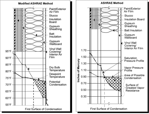
Figure 10a (left). Determining the temperature profile of the exterior wall system identifies the surfaces where condensation will occur. Figure 10b (right). Determining the saturation and vapor pressure profiles of the exterior wall system is also necessary for maximum moisture control because this helps identify wall components that may trap moisture.
Emerging Issues
Current and Future Research and Development
The Building Science Corporation discusses many of the current issues related to building envelope construction for moisture control.
The Air Barrier Association of America provides information related to the science and construction of air barriers.
Relevant Codes and Standards
Currently, the following states have incorporated air barrier requirements into their commercial energy conservation codes.
- MassachusettsDownload 13-energy-efficiency.pdf
- Wisconsin
- Michigan
- Rhode IslandDownload 5981.pdf
- GeorgiaDownload iecc2020_gaamendments_revised03082018.pdf
- MinnesotaDownload 39_47.pdf
- Florida
Additional Resources
Organizations
Publications
- Preventing Moisture and Mold Problems: Design and Construction Guidelines, CH2M HILL, 2003 Handbook of Fundamentals, ASHRAE, Atlanta, GA, 2009
- ASHRAE Guide for Buildings in Hot and Humid Climates, American Society of Heating, Refrigerating, and Air-Conditioning Engineers, Atlanta, 2008


