Introduction
Within This Page
Building control systems are critical to the operation of high-performance buildings. Smart building controls provide advanced functionality through a computerized, intelligent network of electronic devices designed to monitor and control the mechanical, electrical, lighting and other systems in a building. Advanced technology allows the integration, automation, and optimization of any building system in support of facilities management and the building's operation and performance.
A smart controls system often yields significant reductions in operations and maintenance as well as energy consumption. A smart controls systems can control, monitor, and optimize building services, such as, lighting, HVAC, electrical plug-loads, security, CCTV, access control, audio-visual, as well as occupancy-related systems. The traditional Building Management System (BMS) has been the major focus of building controls since the advent of DDC systems. Emerging into the marketplace however, are advanced technology building management platforms with customizable dashboards, innovative software applications, open programming languages, and expanded integration capabilities. These integrated building management systems (IBMS) and smart controls are better suited to maintain a building's performance and address the increased complexity of today's buildings.
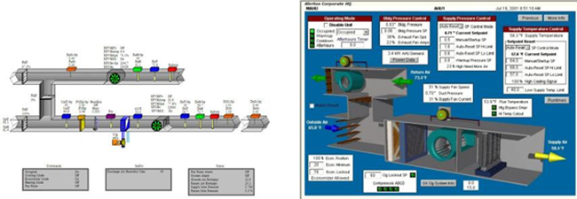
BMS Equipment Copyrights left to right: Affiliated Engineers Inc. and Alerton
Description
Building control systems are the dynamic or active part of the building that monitor, manage, and adjust the environment and performance of the building. There are a variety of control systems in buildings that support occupant comfort, a healthy environment, life safety, security, and the building's basic infrastructure such as electric power and conveyance equipment. These control systems primarily address heating, cooling, ventilation, lighting, power, access to the building, shading, etc.
There are several types of control systems that are or have been deployed in buildings; these include manual controls, mechanical pneumatic control systems which are older, obsolete, and no longer used, controls which use electrical contacts and relays, and Direct Digital Controls (DDC). The DDC control systems process data digitally (regardless if it's digital or analog) and can control terminal devices. DDC is the current industry standard for the major control systems, such as HVAC control and is based on the use of microprocessors, software, and electronic control devices.
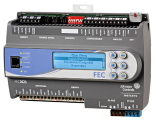
Typical controller Copyright: Johnson Controls
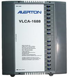
Typical controller Copyright: Alerton
The basic control system monitors field devices and sensors that are connected to controllers or directly to a system headend. The data from the sensors and field devices are inputs to the control system. The data input is processed and compared to the rules and settings for the control system. Based on the input data, the control system will either determine the data is within an acceptable range and the system is operating properly or the data input is outside of an acceptable range triggering the control system to issue commands to change the status of the controlled device. A typical example would be the room temperature being higher or lower than the temperature setpoint. In this case the control system processes that data and commands or manages the equipment (in this case fans and dampers) to get the room temperature back to the setpoint.
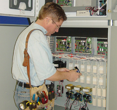
Technician working on controls ( ) Copyright: O.C. McDonald Co., Inc.
Each of the control systems is a network and the systems have some commonality. They all have data points that can be monitored and managed. The systems need cabling and cable pathways or wireless connectivity. The system will use a communications protocol to exchange data within the control system. Many of the systems will have a databases and system administration workstations. In addition, the systems will probably need IP addresses, power, and equipment room space and will generally require web access.
Sensors and transmitters that are part of a control system may include thermostats, liquid differential pressure transmitters for pumps and chillers, differential pressure sensors for fluids and airflow, static pressure sensors, air pressure sensors, CO2 sensors, occupancy sensors, humidity sensors, etc.
These devices may communicate to each other or to the controller with analog or digital signals. Analog inputs to a controller can be a continuously changing signal from an external device or sensor, such as a temperature sensor. Digital inputs to a controller are simply a two-state, on-off signal from external devices or sensors, such as a switch.
In much the same way, analog outputs from a controller are "proportional variable" signals sent by the controller to adjust an actuator or external control device, such as a valve actuator. Digital output from a controller is a two-state or two-position signal from the controller to an actuator, such as control fan relay start-stop switch.
Most field devices and equipment of building automation systems communicate at low network speeds, typically transmitting at rates of less than 1 Mbps. The communications network for a building automation system is typically in a physical star or bus topology from the controller.
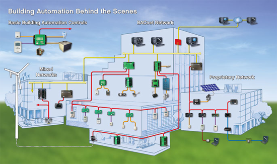
Automation in a building Copyright: EE Times/Buzz
Direct digital control (DDC) is commonly used in more complex HVAC systems. DDC allows for a system controller to compute the sequence of operations based on the digital input from system sensors. Although DDCs are digital controls, they are able to handle analog-to-digital and digital-to-analog conversions.
The controllers are microprocessor-based, and are programmed with the control logic for the equipment it is monitoring and managing. The control logic is the strategy to make a piece of equipment operate properly, using appropriate data inputs and setting the required condition. The control loops can be open or closed. An open loop is a controller obtaining input data, comparing to the control logic of the controller, and then controlling or adjusting the controlled device. A closed loop or feedback loop is when the input data from a device is affected by the controlled device. For example a simple thermostat uses closed loop logic; it monitors the temperature and triggers a control signal until the temperature is at the setpoint. Cascading control loops are a combination of open and closed control loops, using input data from both loops to generally control the closed loop.
Network Architecture
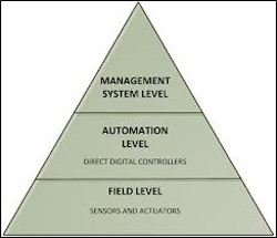
Automation System Levels Copyright: Kastner et al., 2005a
The typical control system network architecture, such as an HVAC control system, consists of several network levels:
- Management Level
- System-Level or Building-Level Controllers
- Field-Level Controllers
The top level of an HVAC control system is typically the building management system (BMS). The BMS is an operator administration workstation that can communicate with, interrogate, and control any of the controllers and devices on the network. A BMS monitors, supervises, controls, and reports on building control systems. These systems may include access control, video surveillance, fire alarm, HVAC control, programmable lighting, and electric power management. Its basic functions are:
- Providing information on those supervised building functions including, but not limited to, current status, archived historical information, summaries, analysis, displays, and reports on control and management functions
- Detecting, annunciating, and managing alarms and other conditions
- Diagnostic monitoring and reporting of system functions, nodes, devices, and communication networks
- Interfacing or integrating between individual building control systems.
These systems typically display the following responses to an operator's workstation:
- Alarm summary
- Event summary
- Trend set displays
- Group control and group trend displays
- System status
- Configuration displays
- Communication links status
- System parameters configuration
- Time schedule assignment
- Holiday assignment
- History assignmet
- Events archive and retrieval
- Time period summary and configuration
- Point detail for every configured point
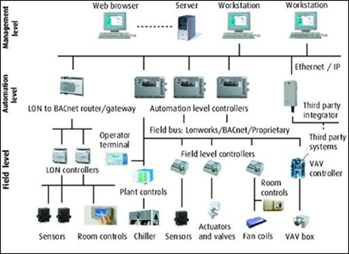
Controls diagram integration - flow chart Copyright: BSRIA Ltd
The system level or building level controllers are networked back to the management level. These controllers can manage HVAC equipment directly (typically, major components such as air handling units) or indirectly through lower-level controllers that are networked downstream. System level controllers handle the operations of all downstream field level controllers, collect and maintain data, and can operate as stand-alone units if communication is lost to the management level. System controllers have a peer-to-peer relationship with other controllers.
Field-level controllers serve building floors, and specific areas, applications, and devices. The field level controllers are typically limited controllers, in terms of both functionality and connectivity.
An important part of current control systems is the use of standardized and open communications protocols. The protocols establish a transparent data format which provides for the exchange of data within and between control systems. The best known communications protocols established by standards bodies and used with control systems are BACnet, LonWorks and KNX. Modbus, a defacto communications protocol, is commonly used in building control system for elevators, meters, and power management.
BACnet is an acronym for Building Automation and Control networks. It is an international data communication protocol developed and maintained by the American Society of Heating, Refrigerating and Air-Conditioning Engineers (ASHRAE). It was first published in 1996. BACnet provides a standard for representing the functions and operation of building automation and control devices. For example, the protocol covers how to request a value from a humidity sensor or send a pump status alarm.
The principle of the development of BACnet was to move away from proprietary communications to similar devices by different manufacturers, and instead treat communications and control of like-devices in a standard common way. This approach and structure allows BACnet to be used in HVAC, lighting systems, fire alarm systems and other building automation systems. BACnet can communicate over several types of networks. These include Ethernet and MS/TP (master-slave/token-passing).
LonWorks is often referred to as a communications protocol for control networks, but because it bundles a communication protocol with a dedicated microprocessor and media transceivers, it is more a networking platform. LonWorks was created by the Echelon Corporation. In 1999 the communications protocol (then known as LonTalk) was submitted and accepted as a standard for control networking (ANSI/CEA-709.1-B). In 2009 LonWorks became an international standard, ISO/IEC 14908. Whereas LonTalk addresses the issue of how devices communicate, LonWorks defines the content and structure of the information that is communicated. The protocol is primarily focused on building and home automation.
Modbus is a communications protocol published by Modicon in 1979. At that time Modbus primarily focused on communication to programmable logic controllers (PLCs) manufactured by Modicon and used in industrial automation. Modicon is currently a company owned by Schneider Electric, and in 2004 the Modbus standard was transferred to a nonprofit organization, Modbus-IDA.
Application
Smart building control can apply to a variety of buildings, spaces and building systems. Building use can range from a modest residential building to large campuses of corporate or institutional buildings. The functional objectives of the smart controls are the same; monitoring and managing the building's environment. Smaller buildings may have pre-packaged controls, such as a home automation system. Larger buildings will have a building management system as well as other specialty control systems such as lighting control or power management. Campuses of buildings are likely to have multiple building management systems as well as specialty systems related to building use (healthcare, education, etc.).
Case Studies
Empire State Building Retrofit
The Mutual Building - Christman Company Headquarters
Emerging Issues
There are several trends and developments in the deployment of smart building controls. One of the most important developments is the continuing penetration of Information Technology (IT) into the building control infrastructure. While this is a positive move it can affect the responsibilities and roles of existing service organizations, such as IT and Facilities Management. Also, traditional building management systems (BMS) that monitor and manage a large number of the building's control systems are now being required to integrate with other systems such as a facility management system and business related applications such as asset management and procurement. The most recent trend is data analytics; essentially managing and analyzing the data from control systems. The objective of analyzing data is to identify the performance of systems and the building. A number of companies have developed real-time analytic software applications for building control systems. The most notable applications are those focused on HVAC systems that can identify faults within a HVAC system and provide diagnostic information.
Relevant Codes and Standards
ASHRAE Standards and Guidelines
- ASHRAE Guideline 11 Field Testing of HVAC Controls Components
- ASHRAE Guideline 13 Specifying Building Automation Systems
- ANSI/ASHRAE Standard 135 BACnet—A Data Communication Protocol for Building Automation and Control Networks
- ANSI/ASHRAE Standard 135.1 Method of Test for Conformance to BACnet
- SPC 201P Facility Smart Grid Information Model Proposed Standard authorized (Albuquerque) June 30, 2010
NIST
Unified Facilities Guide Specifications (WBDG)
- Division 23 - Heating, Ventilating, and Air Conditioning Section 23 09 23.13.20 BACnet Direct Digital Control Systems for HVAC Section 23 09 23, LONWORKS Direct Digital Control for HVAC and Other Building Control Systems
- Division 25 - Integrated Automation Section 25 10 10, Utility Monitoring and Control System (UMCS) Front End and Integration
- Division 26 - Lighting Controls Section 26 09 23, Lighting Controls
Additional Resources
Publications
- Control Design and Functional Testing GuidesDownload FTG-brochure.pdf
- Control Systems & LEEDDownload 096-099_Emerging.pdf
- HVAC Control SystemsDownload usace_hvac_controlsystems.pdf
- Introduction to Commercial Building Control Strategies and Techniques for Demand ResponseDownload 59975.pdf
- Lessons Learned from Case Studies of Six High-Performance BuildingsDownload 37542.pdf
- Lighting Controls in Commercial BuildingsDownload lighting_controls_in_commercial_buildings.pdf


