Introduction
Within This Page
This section outlines the key issues related to the protection of the building envelope against seismic forces. Performance of cladding, glazing and roofing in earthquakes is outlined. Below grade construction is part of the overall structural design of the building and its damage is not discussed here as a separate topic.
Design issues and solutions for heavy, intermediate and lightweight opaque cladding and fenestration are described. Extracts from the International Building Code that govern cladding and glazing are reproduced, together with some commentary, and seismic research on cladding and glazing is reviewed. References to useful publications and industry associations are provided.
Seismic Performance of Wall Systems and Glazing
In light of the extensive worldwide use of heavy cladding systems and fenestration their performance has been good. The possibility of glass breakage and fall out and the detachment of heavy concrete façade panels represent a severe threat to life safety, yet serious casualties have been few. In recent US earthquakes only three deaths have occurred because of falling concrete cladding panels. Falling panels at the J.C.Penney store in the 1964 Alaska earthquake killed two people (Figure 1). In the 1987 Whittier, California, earthquake a student was killed by a concrete panel that fell from a parking structure at California State University, Los Angeles while she walked beneath it (Figure 2).
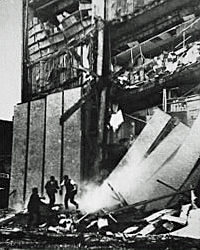
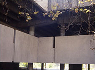
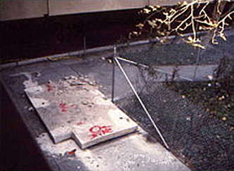
Figure 1. Concrete panels falling from the J.C. Penney store, 1964 Alaska earthquake.
Figure 2. Parking structure, California State University, Los Angeles, Whittier earthquake 1987: Left, panel arrangement; Right, fallen concrete panel, causing fatality.
Metal and glass curtain walls have also performed well, probably because of the inherent strength of glass, the flexibility of the framing assembly, the resiliency of the glass retention materials and the relatively small size of the glass panels. (Figure 3)
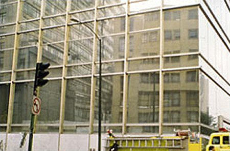
Figure 3. Only minor glass damage occurred to this bank in downtown Mexico City, in one of the areas most severely shaken tin the earthquake of 1985. Note the undamaged mitered glass at the corner.
More severe glass damage has occurred in storefronts, where glass panes are often large, the lateral movement of the building extreme and the quality of glass installation may be deficient, particularly in older buildings.
However, the design and installation of cladding systems needs great care because successful performance depends on solving problem of the interaction between cladding and building structure during a seismic event. The building stock of a major U.S city has not yet been tested by more than a moderate earthquake. The magnitudes of both the Loma Prieta and Northridge earthquakes were well below those that may be expected in the future, and there were few large buildings close to their epicenters.
Seismic Performance of Roofing Materials
Experience in the Northridge earthquake showed that, because of its weight, heavy tile is vulnerable to displacement unless adequately secured to the deck. Nevertheless, most of the tile roofs in Northridge performed well and exhibited no signs of damage. Failures included tiles falling to the ground and tiles shaken out of position that required repair. Failures were due primarily to inadequate design (lack of attachment), or various types of workmanship deficiencies, and occurred primarily to tiles attached to wooden decking.
Since Northridge is a low-wind speed zone some of the roof designs simply provided for the tiles to be loose-laid on battens. Under moderate seismic conditions this proved to be inadequate and tiles were displaced horizontally, sliding down-slope.
Description
Heavy Cladding Systems
Heavy cladding systems consist typically of precast concrete: they may also have additional attached facing materials such as natural stone or ceramic tile.
Seismic codes require that heavy panels accommodate movement either by sliding or ductile connections. In high seismic zones sliding connections are rarely used, because of the possibility of incorrect adjustments when bolts are used, jamming or binding due to unwanted materials left after installation and jamming due to geometrical change of the structural frame under horizontal forces. Any of these causes may result in failure of the sliding faces that may be called upon to work instantaneously decades after their installation. (Figure 4)
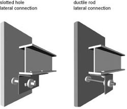
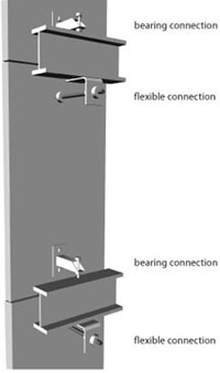
Figure 4. Examples of sliding (left) and push-pull (right) connections. Based on Wang, 1971
Figure 5. Typical floor-to-floor push-pull panel connections. Each beam has a bearing connection at the bottom of a panel and a flexible, or tie-back, connection for the panel below.
The need for disassociating the heavy panel from the frame has a major impact on connection detailing. As a result, a connection commonly termed "push-pull" has been developed, primarily in California, which provides, if properly engineered and installed, a simple and reliable method of de-coupling the panel from the structure. The generic connection method consists of supporting the panel by fixed bearing connections to a structural element at one floor to accommodate the gravity loads, and using ductile "tie-back" connections to a structural element at an adjoining floor. (Figure 5)
The tie-back connection is designed to deform under lateral forces and thus does not transmit racking forces to the panel. The tie-back must be capable of accommodating the out-of-plane forces on the panel, including wind.
A typical arrangement of push-pull type panel supports is shown in Figure 6.
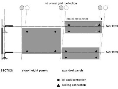
Figure 6. Typical arrangement of connections for push-pull type panel support: Left, section showing gravity load connections at top of panel; Center, elevation of panel showing location and type of connection; and Right, location and type of connections for spandrel panel.
The bearing connections can be located either at the top or bottom of the panel. Some engineers believe that when the bearing is at the bottom of the panel the location presents a risk: if the tie-back connection fails the panel may rotate outwards and fail. Figure 6 also shows (center) a typical connection layout for a panel. The bearing connection generally consists of sections of steel angle or tube, depending on the load. A stud bolt is provided for adjustment and temporary support until final alignment, after which the assembly is welded.
Deep spandrel panels, that do not span floor to floor, are supported in the same way, with fixed and ductile connections, to accommodate possible deformation of the supporting under severe earthquake forces. This is also shown in Figure 6 (right). The ductile connections also provide a simple means of aligning and leveling to panels. A typical deep pre-cast spandrel attached to a steel structure is shown in Figure 7. Narrow spandrel panels may have fixed connections to a structural member, and the inter-story drifts are then accommodated entirely by the glazing system.
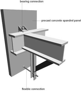
Figure 7. "Push-pull" connection for a deep pre-cast spandrel attached to a steel beam. Bearing connection at top, tieback connection at bottom.
Column covers are also supported by fixed and ductile connections, to accommodate possible deformations in the columns. Figure 8 shows a connection pattern for a column cover.
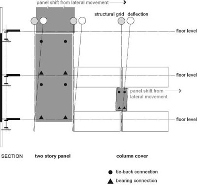
Figure 8. Connection arrangement for a column cover. (after PCI)
The use of ductile connections to allow for movement is the most significant feature of these details The push-pull connection is easily calculated and designed and is reasonably fool-proof in installation, since it is relatively independent of the individual installers skill for its safety. The extensive dependence on welded gravity connections relies on good welding techniques by the installer but these connections are exposed and simple to inspect before closing up. By contrast, sliding-type details depend on correctly torqued bolted connections or critical clearances within slotted holes that require care, skill and understanding to execute correctly.
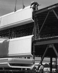
Figure 9. Erection of precast concrete panels with push-pull connections.
The push-pull connection also represents one of the simplest ways of obtaining installation adjustments that are necessary for panel alignment, irrespective of seismic requirements. Since time is very costly in a competitive business environment, the need for connections that can be quickly installed is a major concern. Large pre-cast panels, using typical detailing, can be installed in less than 10 minutes per panel for low-rise construction and around 15-20 minutes for high-rise. This represents the time required for one cycle of panel installation, from lifting the panel from the ground (or truck), its placement, adjustment, and the removal of the lifting tackle. (Figure 9)
Connections must be designed for safe temporary support while the panel is being adjusted, leveled vertically and horizontally and correctly spaced in relation to adjoining panels. Some installers complete the full panel installation, including welding, at the same time as the initial panel placement is done. In high-rise building, however, it is common to provide temporary placement for a large number of panels, before another crew returns to adjust and make final connections. The latter process maximizes use of the crane and operator. However, during final installation the panels are vulnerable to wind and seismic forces.
Casting, handling and erection economy mandates the use of the largest possible panels (subject to weight and transportation restrictions). The connections are expensive, both in construction and erection, and so the use of large panels reduces the number of connections. However, seismic requirements are in conflict with the use of very large panels because of the larger dimensional deformations in the main structure that must be accommodated. While in non-seismic areas two or three story height panels are used, normal practice in seismic zones is to use panels that are limited to one story in height and seldom more than one horizontal bay in width.
Since the panel connections, of which there may be hundreds or even thousands, are relatively expensive, designers sometimes reduce the number of connections necessary by varying to shape of the panels. Figure 10 shows a number of panel layouts, including the use of specially shaped panels, such as L-shape and T-shape, to reduce the number of panels and connections.
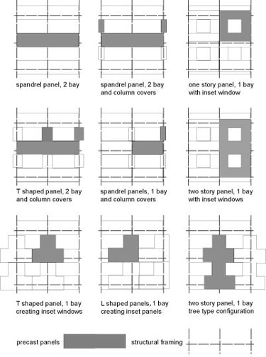
Figure 10. Panel façade layouts, including some designed to reduce the number of panels and connections (see, e, f, g, h, i).
Figure 11 shows an L-shape panel together with a parapet wall and its connections, and illustrates the complexity that may be necessary to achieve a satisfactory detail. The parapet panel is similar to a spandrel panel: the fixed connection is shown at the top and the ductile connection at the bottom.
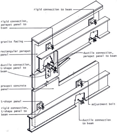
Figure 11. L-shape panel and its connections. after Forell/Elsesser Engineers
The sophistication of this level of details means that their design and delineating becomes a major task. The set of structural construction documents from which this group of figures was developed comprised over 100 sheets, prepared by a structural engineer consulting to the pre-cast panel supplier.
Another technique for reducing the number of panels and connection is to support a number of facing panels on a metal frame that is attached to the building structure. The frames can be shop welded: a number of facing panels are attached at the site and the entire assembly is then lifted up and attached to the structure. Figure 12 shows a large spandrel panel assembly constructed in this way, using natural stone facing panels.
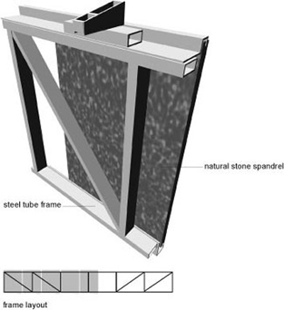
Figure 12. Spandrel assembly of natural stone mounted on a metal frame.
All these connection details are based on engineering principles and experience and represent a design response to accommodating the forces required by the seismic code. Vast numbers of these connections have been installed in the field, with a whole variety of configurations and details that have not been tested. Most engineers have developed typical details, but architectural requirements often require building-specific detailing. While the general concepts and execution of these details suggest that that they will perform safely in earthquakes there are a number of questions that might be answered by experimental test programs.
- The typical connection detail is based on the concept that permits the structure to move independent of the panel. However, in successive floors, panels will move relative to one another. Slight dimensional variations or rotation of the beams may result in these panels touching with resultant undesirable interaction.
- The typical detail is based on a two-dimensional concept that works for a limitless plane of panels. However, at outside and reentrant corners the problem becomes three dimensional and impact between the panels is possible under large drifts. (Figure 13) Use of larger gaps at reentrant corners and mitered panels at outside corners helps to relieve this possibility. Figure 14 shows an alternative detail for solving the corner problem.
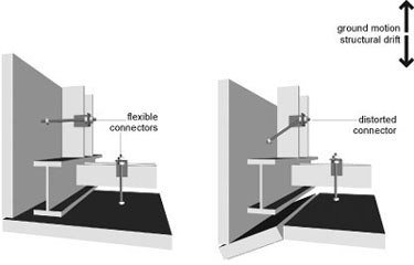
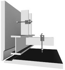
Figure 13. The cladding corner problem. Depending on the motion, panels may impact.
Figure 14. Typical detail for the attachment of corner panels showing mitered corner to permit panels to slide past one another with minimal damage.
- Typical design of spandrel panels requires that the entire inter-story drift must be accommodated in the glazed space between the spandrels. Since this glass height is often less than one-half the floor-to-floor height the actual drift experienced by the glass may be more than double the design drift. While the detail may protect the panels, the exaggerated drift may difficult for the glazing to accommodate, particularly at reentrant corners. This condition is now accounted for in the seismic code. (Figure 15).
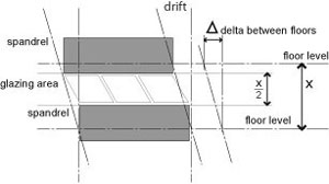
Figure 15. Diagram showing glass forced to accommodate the full height drift. Design interstory drift ratio is based on story height X. But connection of spandrel panels requires glazing to accommodate story drift in height X/2 or double the design story drift.
- Large irregularities in vertical and horizontal configurations (high floors, set-backs, reentrant corners) can create serious problems of torsion and stress concentration that will result in distortion and drifts beyond those that the cladding can accommodate. Careful scrutiny of these conditions is necessary at an early design stage to ensure that the cladding detailer is not faced with conditions that may be almost impossible to make safe.
- Weather protection of metal connections is an important long-term consideration, particularly in coastal regions with relatively salt-laden air. Current detailing methods generally result in a concealed connection once the building is finished, though bottom connections are sometimes revealed when ceiling panels are removed. Weather protection is accomplished by caulking butted joints: edge profiles that incorporate weather stops and drips are little used. This results in simpler forming and casting, with less likelihood of delicate edge sections fracturing upon formwork removal. However, prevention of moisture penetration is entirely dependent on the long-term integrity of the sealant.
Glass Fiber Reinforced Concrete (GFRC) Cladding Systems
Glass fiber reinforced concrete (GFRC) is a cladding material of intermediate weight now in frequent use. The term is applied to products manufactured using a cement/aggregate slurry reinforced throughout with alkali resistant glass fibers. The material is applied in a spray-up process under controlled factory conditions. The material is a composite with reinforcing elements randomly distributed throughout the matrix, unlike reinforced concrete in which the reinforcing is placed only in tensile stress areas. GFRC architectural panels generally weigh from 10 to 25 pounds per square foot (48 kg/m² to 121 kg/m²) depending on surface finish, panel size, shape and arrangement of the steel stud or tube framework. This is approximately one third to one quarter the weight of pre-cast concrete, so that seismic forces are substantially reduced.
Typical single-skin GFRC panels have a backing thickness between 1/2 and 5/8 in. (13 to 16 mm), not including the exposed aggregate for mix or veneer finish. For large panels it is necessary to provide stiffening ribs, either integral with the material or by providing a metal sub-frame on to which the single skin material is adhered during fabrication. The GFRC material must also be thickened to provide inserts for connections. The panels are installed in a similar way to pre-cast concrete. Figure 16 shows a typical GFRC spandrel design and attachment.
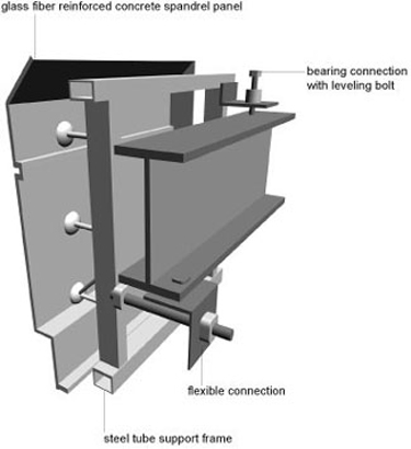
Figure 16. Typical GFRC panel and attachment (after PCI).
GFRC panels are generally limited in size because the material undergoes thermal movement approximately double that of concrete. This must be allowed for in fixing through the use of Teflon washers or other means. Accommodating this requirement is also beneficial from a seismic viewpoint.
Light-Weight Panel Systems
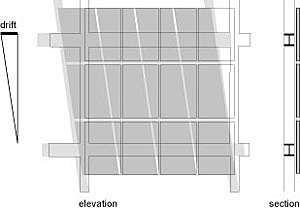
Figure 17. Elevation of relationship between curtain wall and structural drift. The grid assumes a parallelogram shape: glazing must provide sufficient space between glass and frame to ensure that contact does not occur.
Lightweight cladding is generally designed to move with the structural frame and must be able to accommodate design drifts. In the case of a full metal and glass curtain wall system the opaque portions will often use the same glazing as the transparent areas, with reflective or dark glass backed-up by insulation. Another common type of light-weight cladding is that of horizontal alternating bands of glazing and metal insulated panels. The latter may be a spandrel wall built on site from steel studs with metal facing, or it may consist of factory fabricated panels, with exterior facing, insulation and interior finish assembled into an integrated panel. In either case the floor -to-floor drifts must be accommodated by the glazing system, and deformation in the spandrel panels accommodated at the vertical joints between the panels (Figure 17). Sometimes curtain walls in seismic regions are designed to accommodate in-plane racking motions by providing slip joints between adjacent panels.
The opaque elements of light-weight exteriors, whether metal curtain wall assemblies or low cost assemblies of steel studs faced with EIFS assemblies, stucco, brick tiles or ceramic tiles, are generally not isolated in the same way as heavy panels. While these assemblies may suffer considerable damage due to distortion of the main structure, the possibility of large-scale drop-off and danger to lives is not as great as for heavy cladding systems although falling brick tiles or other sheet material would present some degree of risk. See also the Building Envelope Design Guide for more information on Wall Systems.
Windows and Curtain Walls
Experience in earthquakes has shown that glass has considerable in-plane strength and out-of-plane flexibility. (Figure 18)
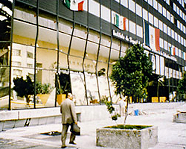
Figure 18: Glass damage in Mexico City earthquake, 1985. Note the extreme distortion of the first floor, but only a few glass panels were severely damaged. Even with the massive shaking, glass in the upper floors is undamaged.
Glass is, however, vulnerable to forces applied to its edges and corners by rigid framing members. Earthquake forces cause the structure to drift, and in a typical curtain wall in which the framing is rigidly attached to the structure framing system deforms and corners of the glass may impact the metal frame. (Figure 19)
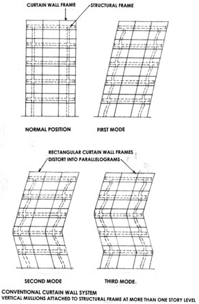
Figure 19. Vibration modes of a typical building frame and its relationship to curtain wall. after Brueggman et al. 2000
Current techniques depend on the care of the field installer to ensure that adequate clearances are maintained, rather than using connection details that allow for movement of the curtain wall framing independent of the main building structure. Glass is retained within the frame by flexible gaskets and clearance between glass and frame is maintained by inserting small rubber block spacers. The flexible gaskets and rubber spacers allow for considerable movement of the glass within the frame and the rubber blocks must be compressed before the glass impacts the metal. Figure 20 shows the arrangement of glazing support within a metal frame to ensure correct glass/metal clearances.
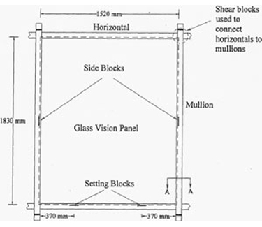
Figure 20. Elevation of glazing installed in a metal frame. Note side blocks and setting blocks to ensure adequate space between glass and frame. Behr, 2004
The architect usually specifies minimum clearances determined by analysis required by the seismic code. Field checking of clearances during installation by the architect or engineer is critical to ensure good seismic performance. Once the glazing is installed, inspection is virtually impossible. Figure 21 shows a typical glass framing detail.
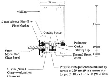
Figure 21. Typical glass framing detail. Behr, 2004
When window glazing is inserted into concrete panels, or inserted between stiff structural members or sub-frames, the need for the glazing to accommodate racking forces is negligible. Window elements with factory installed glazing are likely to have better quality control than site installed glazing.
Fundamentals
Below Grade Envelope
Since below grade construction and basement walls and floors are elements of the main building structure their seismic safety is a provision of the structural design and construction of the building. The recent development of base isolation as a means of seismic protection may substantially change the below grade design characteristics of the building, although the below grade retaining wall structure will remain the same.
Base isolation works by detaching the building superstructure from its foundation and supporting it by a set of bearings, which are either of specially formulated resilient material or Teflon coated stainless steel. This decoupling changes the response characteristics of the building and greatly reduces the accelerations while increasing the displacement. A typical base isolated basement design requires a space of between about 12 to 24 inches in which the building is free to move sideways without hitting the surrounding structure. This space is commonly referred to as the "moat". Any services that enter the building must make provision for these large displacements, either by flexible joints or large radius expansion loops. The moat must be covered, either by sacrificial material or have the ability to slide over the adjoining supports. Figure 22 shows the typical arrangement of a base isolated building with the isolators located below the basement floor.
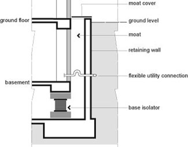
Figure 22. Diagrammatic section through base-isolated building. Note the moat, shown with a sliding cover and provision for flexibility in the entering services. The moat may be from 12 to 24 inches wide.
Roof Envelope
Roofing finish materials for large buildings have little influence on seismic performance beyond including them in weight estimates for analytical purposes: this is minimal compared, for example, to the seismic issues created by use of a heavy ceramic tile roof on a wood frame house.
Care should be taken to ensure positive attachment of the roof covering to the structure in the event the roof framing distorts under seismic loads.
Properly executed standard practice for roofing attachment should prove adequate for lighter weight steep-slope coverings such as asphalt or wood shingles and metal, and for low-slope coverings, including heavy coverings such as aggregate or paver ballast. For aggregate of paver ballasted systems standard practice is to have a parapet or raised edge that extends above the height of the aggregate or pavers: this should be sufficient to retain the aggregate or pavers but to ensure containment of the material a parapet with a minimum height of 6 inches is recommended.
For securing ceramic tile, cement-fiber tiles or slate the following attachment guidance is recommended where the design roof acceleration exceeds 0.5 g.
- When tiles are loose-laid on battens supplemental mechanical attachment should be provided.
- Tiles nailed only at the head may not perform well. If they are attached with a smooth-shank nail into a thin plywood or oriented strand board (OSB) deck, pullout can occur. Ring-shank or screw-shank nails or screws should be specified, but in addition wind clips near the tail of the tile should be used to prevent "bounce" which causes enlargement of the nail hole by repeated pounding.
- Tiles attached by only one fastener may experience eccentric loading. Wind clips should be specified for attachment near the tail of the tiles.
- Two-piece ("mission") tiles attached with straw nails can slide down-slope a few inches because of deformation of the long straw nail. A wire-tied system or proprietary fasteners not susceptible to down-slope deformation should be specified.
- When tiles are cut to fit near hips and valleys, the portion of the tile with nail hole(s) is often cut away. Supplemental attachment is necessary to avoid displacement of these tiles.
- Attachment of rake, hip and ridge tiles with mortar is ineffective and should be augmented with mechanical attachment.
- Rake trim tiles fastened close to the head of the tile often slip over their fastener because repeated pounding enlarges the nail head. Additional restraint should be provided.
- For roofs within 3,000 feet of the ocean stainless steel fasteners are recommended.
Large roof lights and atria need special seismic detailing that typically is part of the glazing design.
When egress openings occur below steep-slope or mansard tile, cement-fiber or slate roofing, a canopy should be designed over the exit paths to provide protection from falling roof coverings.
Exterior Skin Envelope
The exterior skin comprises both opaque and transparent materials. When the exterior wall envelope is formed by structural walls provision for seismic safety is a function of structural design and is governed by requirements of the seismic sections of the building code. The seismic loads to be accommodated and some details of seismic design will vary depending on whether the project is located in a high, moderate of low seismic zone. The stiffness of shear walls is such that floor- to-floor drift or deformation is negligible and elements attached to the walls are subject only to acceleration forces. Commonly used methods of the attachment of additional facing materials to the building structure, if correctly designed and installed, will ensure safe seismic performance under design accelerations.
A wide range of cladding methods for framed structures is in common use. There has been both an aesthetic and a technological evolution in the last few decades, and a distinction has arisen in the design of opaque exterior cladding elements that are attached to framed structures: that between heavy, intermediate and light-weight elements. Whereas until the early seventies pre-cast concrete elements tended to dominate the market, the technological development of glass fiber reinforced concrete enabled similar and even more sculptured forms to be more economically produced. The relatively light weight of this material, which can have the appearance of architectural pre-cast concrete, made it particularly suitable in earthquake-prone regions.
At the same time developments in glass technology enabled metal and glass curtain walls to become both more energy efficient and refined in appearance and new adhesives enabled the glass to be glued to the face of the metal frames, thus eliminating the exterior framing pattern completely, if the architect desired to do so.
The use of light-weight metal faced insulated panels, has become characteristic of many commercial buildings, in conjunction with curtain wall glazing. Other lightweight systems are built up on site, in the form of steel stud walls with inserted or applied insulation and metal faced panel or stucco facing.
Of all the elements of the building envelope heavy pre-cast concrete wall cladding panels attached to steel or reinforced concrete frame structures require the most design and construction attention to ensure seismic safety. These typically span from floor-to-floor: horizontal drift or deformation of the building structural frame can create considerable racking forces in panels that are rigidly attached at top and bottom, resulting in damage or possible drop-off. Therefore the attachment of these panels must permit differential movement of the floors without transmitting racking forces to the panels. This is achieved by special detailing of the connection of panels to structure.
Metal/glass curtain walls that span from floor-to-floor face a similar problem but their greater flexibility, lighter weight and resilience render the problem less severe. Typical framed window glazing inserted in structural walls is not subject to the racking problem due to the stiffness of the wall.
The evolution of cladding design and its attachment has been accomplished primarily by practicing engineers, industry groups and product suppliers. Seismic design methods for curtain walls have been developed by specialist consultants, manufacturers, and installers and by research into resilient and adhesive materials for glass retention. The later work has not been specific to seismic issues since protection against wind is also a major factor in glazing design problems. The seismic problem is primarily that of protection from in-plane forces while that of wind is primarily concerned with out-of plane effects. The design of effective resilient glass retention systems contributes to the solution of both.
Emerging Issues
Research on seismic cladding and glazing has been limited, and until recently concentrated on evaluating cladding and glazing systems in common use.
Cladding Research
Only a few researchers have conducted experimental research on the performance of currently used cladding systems.
Wang (1987) conducted research on the seismic behavior of curtain wall cladding elements on a full scale test frame. Both slotted hole and push-pull systems were tested. Rihal (1988a), 1988b, conducted studies of the seismic behavior and design of pre-cast façades/cladding and push-pull connections in low/medium rise steel frame buildings, including experimental testing.
A significant continuing direction in heavy cladding research is that of the study of panel frame interaction: an allied field of study is that of the use of cladding as an integral part of a lateral bracing system.
Thiel et.(1986) published a feasibility study on seismic energy absorbing cladding systems. Henry and Roll, (1986) conducted analytical studies of cladding frame interaction. Sack et al (1989) conducted experimental studies on cladding /frame interaction. Pall (1989) researched and developed a friction-damped connection for pre-cast concrete cladding. The connection has been used in several projects.
The current main researcher in this area is Goodno and his team at Georgia Institute of Technology, for example Goodno et al. 1989, and Pinelli et al. 1993. Goodno et al 1998 describes the analytical and experimental studies of several developments of "advanced" cladding connectors. Results showed that either up to 41% reduction in peak displacement response could be achieved from the baseline (as-built) configuration by retrofitting advanced cladding connectors, or else as much as a 27% reduction in structural weight (in the longitudinal direction) could be achieved for the same baseline response level. (Figure 23)
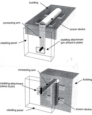
Figure 23. Type of advanced cladding connector: Top, Horizontal; Botton Vertical. Goodno et al, 1998
This advanced connection is capable of developing good energy dissipation qualities through torsional deformation, in a similar manner to the torsion bars in an automobile suspension. The torsion device consists of circular torsion element mounted inside a concentric tube and attached to a vertical surface of a building structure (in the bottom figure above). The outer tube supports the torsion element and fixes it at the lower end, providing rotational bearing support at the upper end of this figure. An arm connected to the torsion element is used to convert the inter story drift (left-right in the illustration) into rotation. The arm is attached to the cladding panel (shown in wireframe mode) with a pin and clevis. The upper figure shows a horizontal application.
Selected Research References
- Goodno, B.J., Craig, J.L, and Zeevaert Wolff A., (1989) "Behavior of Heavy Cladding Components in the Mexico Earthquake", Earthquake Spectra, EERI,Vol 5 No.1, February 1989, pp. 195-222, Earthquake Engineering Research Institute, Oakland, CA.
- Goodno, B.J., Craig, J.I., Dogan, T., and Towashiraporn, P., (1998), Ductile Cladding Connection Systems for Seismic Design, Report GCR 98-758, Building and Fire Research Laboratory, NIST, Gaithersberg, MD.
- Henry, R.M., and Roll, F., (1986), "Cladding-Frame Interaction" Journal of Structural Engineering, ASCE, Vol 11, No 2, April pp. 815-834.
- Nagaki, S.D., and Englekirk, R.E., (1991) "PRESS Industry Seismic Workshops: Concept DevelopmentDownload PRESSS%20Industry%20Seismic%20Workshops-Concept%20Development.pdf" PCI Journal, Vol 36, No. 5, pp. 54-61, September-October 1991.
- Pall, A.S., (1989), "Friction-Damped Connections for Precast Concrete Cladding," Proceedings, Architectural Precast Concrete Cladding—Its Contribution to Lateral Resistance of Buildings, PCI, Chicago, IL. pp. 300-309, November.
- Pinelli, J-P. Craig, J.I., Goodno, B.J., and Hsu, C-C. "Passive Control of Building Response Using Energy Dissipating Cladding Connections," Earthquake Spectra, EERI, Vol. 9, No. 3, August 1993, pp. 529-546.
- Rihal, S., (1988a), "Seismic Behavior and Design of Precasar Facades/Cladding and Connections in Low/Medium Rise Buildings" Report ASCE R88-1, Arch.Eng. Dept. School of Arch. And Envir'l Design, CA Polytechnic University, San Luis Obispo, CA, November.
- Rihal, S., (1898b) "Earthquake Resistance and Behavior of Heavy Facades/Claddings and Connections in Medium-Rise Steel Framed Buildings," Proceedings, Ninth World Conference on Earthquake Engineering, Tokyo-Kyoto, Vol VI, pp202-212, August.
- Sack, R.L., Beers, R.J., and Thomas, D.L., (1989), "Seismic Behavior of Architectural Precast Cladding", Proceedings, Architectural Precast Concrete Cladding-Its Contribution to Lateral Resistance of Buildings, PCI, Chicago, IL. pp. 141-158, November.
- Thiel, C.C, Elsesser, E., Lindsay, J., Bertero, V.V., Filippou, F., and McCann, R., (1986), "Seismic Energy Absorbing Cladding System: a Feasibility Study," Proceedings, ATC-17 Workshop and Seminar on Base Isolation and Passive Energy Dissipation, ATC, San Francisco, CA March, pp. 251-260.
- Wang, M.L., (1987), "Cladding Performance on a Full-Scale Test Frame", Earthquake Spectra, EERI, Vol. 3, No.1 pp. 119-173, February.
Glazing and Curtain Wall Research
Study of the behavior of glazing under seismic conditions has also been limited. Bouwkamp and Meehan (1960) investigated the performance of window panels subjected to racking loads. Cupples, (1985) performed racking tests on a Robertson-Cupples curtain wall system to evaluate the overall performance of the wall system and evaluate the glass-to-frame connection details. Lim and King (1991) investigated the seismic performance of curtain wall systems at the Building research Association of New Zealand, including in-plane dynamic racking tests on full-scale glass and aluminum curtain wall assemblies.
In the early 1990s Richard Behr and a team at the University of Missouri, Rolla and later at Pennsylvania State University, University Park, began a long-term program of experimental testing of the seismic behavior of a number of glazing systems. These included store-front glazing, curtain walls with a variety of glass types and glazing techniques, and glazing with applied film. This work led to a number of recommended revisions to the NEHRP Recommended Provisions for the Seismic Regulations for New Buildings and Other Structures (*FEMA 302) which were published in the 2000 NEHRP Provisions (*FEMA 368). Members of the team participated in developing a recommended Dynamic Test Method for Determining the Seismic Drift Causing Glass Fallout from a Wall System, published as AAMA 505.6-01 and referenced as Recommended Static Test Method for Evaluating Curtain Wall and Storefront Systems Subjected to Seismic and Wind Induced Inrterstory Drifts in the 2000 NEHRP Provisions.
*Update: FEMA 302 and FEMA 368 have been replaced with FEMA 450 and FEMA 451The new NEHRP seismic design provisions for glass and the new AAMA seismic test method for glass have been adopted (in a slightly modified format) in American Society of Civil Engineers (ASCE) 7-02 Minimum Design Loads for Buildings and Other Structures, which is referenced in the International Building Code and NFPA 5000: Building Construction and Safety Code®.
Current research by the team includes a study of the use of rounded corners on glass panels to reduce damage. Tests have revealed significant gains in accommodation of drift. (Memari 1992)
Another investigation has resulted in the development of an "Earthquake-Isolated Curtain Wall System (EICWS)" that de-couples each story level of the system structurally from adjacent floor levels Figure 24 shows the response of the isolated curtain wall frames to a number of modes of vibration. Figure 25 shows how a seismic "decoupler" joint is able to accommodate relative inter story movements while still maintaining a building envelope weather seal. In-plane and out-of-plane movements are accompanied by horizontally continuous, flexible, elastomeric gasket loops that act as weather seals between stories.
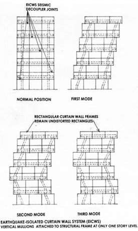
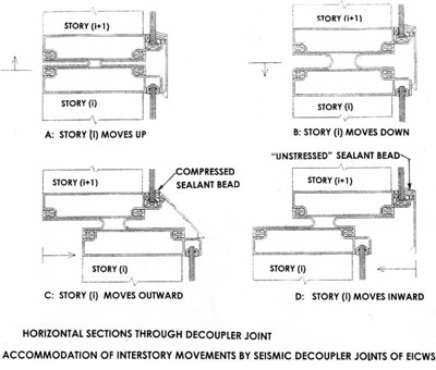
Figure 24. Earthquake-isolated curtain wall system schematic, showing diagrammatic response at first, second and third modes of vibration. after Brueggman et al, 2000
Figure 25: The Earthquake-Isolated Curtain Wall System (EICWS), detail of the decoupler joint. after Brueggman et al. 2000
Selected Research References
- Behr, R.A., (2004), "Design of Architectural Glazing to Resist Earthquakes", Proceeding, 13th World Conference on Earthquake Engineering, Vancouver BC, August.
- Bouwkamp, J.G. and Meehan, J.F., (1960), "Drift Limitations Imposed by Glass." Proceedings of the Second World Conference on Earthquake Engineering, Tokyo, pp. 1763-1778.
- Brueggeman, J., Behr, R., Wulfert, H., Memari, A and Kremer, P (2000), "Dynamic Racking Performance of an Earthquake-Isolated Curtain Wall System", Earthquake Spectra, EERI, Vol. 16 No. 4, November 2000, Earthquake Engineering Research Institute, Oakland, CA.
- Cupples (1985) "Curtain Wall Tests for Cupples Horizon Series of World Wall." Cupples test report No. STL-33, St. Louis, MO.
- Evans D., and Ramirez, F.J.L, (1989), "Glass Damage in the 9 September 1985 Earthquake Mexico City". Lessons Learned from the 1985 Mexico City Earthquake, ed. V. Bertero, EERI, Oakland, CA p233.
- Lim, K., and King, AB, (1991) "The Behavior of External Glass Systems Under Seismic In-Plane Racking," Building Research Association of New Zealand (BRANZ) Study Report, No.39.
- Memari, A.M., Kremer, P.A., and Behr, R.A., (2002)"Architectural Glass Panels with Rounded Corners to Mitigate Earthquake Damage" Dept. of Architectural Engineering, Pennsylvania State University, University Park PA.
Relevant Codes and Standards
- International Building Code by the International Code Council Inc (ICC). Falls Church, VA—Check the following provisions:
- Attachments
- Drift limits (Table 1617.3)
- Architectural Components Coefficients (Table 1621.2)
- Exterior Wall Elements and Connections (§1621.2.3)
- Out-of-plan-bending (§1621.2.4)
- NFPA 5000: Building Construction and Safety Code® by the National Fire Protection Association (NFPA). Quincy, MA.
- ASCE 7 Minimum Design Loads for Buildings and Other Structures by the American Society of Civil Engineers. Reston, VA—Seismic test provisions for glass (§9.6.2.10).
Additional Resources
Publications
- Architectural Precast ConcreteDownload PCI_Architectural_Precast_Concrete_Manual.pdf 3rd Edition. . Precast/Prestressed Concrete Institute (PCI). Chicago, IL, 2007.
- Literature Review on Seismic Performance of Cladding SystemsDownload b95056.pdf by J.M. Cohen. National Institute of Standards and Technology (NIST), Gaithersburg, MD, 1995.
- Earthquake Spectra, Northridge Earthquake Reconnaissance Report, Vol 1, Chapter 11 "Nonstructural Damage". J.F. Hall, editor. Earthquake Engineering Research Institute, Oakland CA, 1995.
Websites
- Mitigation Clearinghouse—The Clearinghouse serves to provide a dynamic resource library, thereby improving discovery and accessibility of mitigation related literature.


