Introduction
Within This Page
Development of new technologies during the 1990's, including affordable microprocessors and increased computer literacy in the work force, has made it possible to determine the actual condition of equipment and not have to rely upon estimates of when the equipment might fail based on age. These new cost effective technologies and the lack of correlation between age and failure in many equipment items have increased the emphasis on Predictive Testing and Inspection (PT&I) also known as predictive maintenance or condition based maintenance (CBM). This technology has resulted in many operations and maintenance (O&M) organizations need to review existing Preventive Maintenance (PM) and Programmed Maintenance (PGM) efforts and ensure that the most effective approach is being used.
PT&I use in operations assessments can help facility managers reduce and prevent unnecessary maintenance. It uses primarily non-intrusive testing techniques, visual inspection, and performance data to assess machinery condition. This allows facility managers to replace arbitrarily timed maintenance tasks with maintenance that is scheduled only when warranted by equipment condition. Continuing analysis of equipment condition-monitoring data allows facility managers to plan and schedule maintenance or repairs in advance of catastrophic and functional failure. Since PT&I does not lend itself to all types of equipment or possible failure it is one of many practiced maintenance modes.
CBM has proven capable of aiding facility managers in identifying anomalies early enough to minimize the impact of operational interruptions; avoid expensive failures, including collateral damage; and significantly reduce the cost of maintenance. Many leading companies in the manufacturing, process, paper, and power generating industries have shifted the majority of their maintenance tasks from time-based preventive to condition based. Commonly mentioned objectives are CBM greater than 50 percent of total maintenance, 25 percent or less time-based PM, and less than 15 percent reactive maintenance on failure. Real returns—in terms of increased operating effectiveness and reduced costs—of five to seven times the annual cost of equipment and labor are typically reported across a broad range of industries.1
Condition measurement and assessment technology, methods, and practice are proven. Applied correctly, all work well in a variety of situations for a variety of people. Some successful programs use engineers. Many more are operated entirely by hourly craftspeople. Michael Neale and Associates, a United Kingdom (U.K.) consulting firm, developed a method for quantifying the value of CBM in 1975.2 As reported by the EPRI, they determined that CBM adds an additional 8 to 12 percent to the savings gained from a good preventive maintenance program. Many companies report significantly better results; some state that a mature CBM program can reduce maintenance cost by 50 percent when compared to reactive, operate-to-failure maintenance.
Often a difficult concept for management to accept is avoiding cost to estimate the true value of CBM. Many of the organizations that report a high value of avoided cost are operating with sold out production in areas where interruptions are extremely expensive as a result of lost production and/or penalties for non-delivery.
CBM can:
Warn of most mechanical problems in time to minimize unexpected failure, the risk and consequences of collateral damage, and adverse impact on safety, operations, and the environment
- Increase equipment utilization and life; minimize disruption to mission and schedule
- Reduce maintenance costs—both parts and labor
- Allow safe elimination of a significant amount of PM
- Minimize cost and hazard to equipment as a result of unnecessary overhauls and disassemble and inspect PM.
CBM cannot:
- Eliminate defects and problems, or stop machines from deteriorating.3
- Eliminate all PM (e.g., lubrication, leak inspections, gas turbine combustion path inspections, and thermographic inspection of electrical connections).
- Reliably and effectively warn of fatigue failures (with current technology).
- Address electronic failures within computer, control, communications and information systems.
- Reduce personnel or produce a major decrease in lifetime maintenance costs without a commitment to eliminating defects and chronic problems.
Description
Condition monitoring measurements or PT&I are conducted utilizing a variety of technologies. Vibration Analysis, Infrared Thermography, Oil (Fluid) Analysis, Electrical Analysis, and Ultrasonic Measurements are considered the core predictive testing and inspection technologies. Training is available through various sources and certifications in the individual technologies can be obtained via vendors or non-manufacturer affiliated organizations such as The American Society of Non-destructive Testing (ASNT). ASNT has overall standards for conducting PT&I training. Individual facilities personnel can become certified as level I, II, or III in various technologies. The standard for conducting training is SNT-TC-1A and can be obtained by contacting the institute.4
A. Progressive Techniques
General industry-wide application of predictive testing and inspection technologies are detailed as follows. Many approaches such as dynamic vibration and lubricating oil analyses are well known and widely used, while others such as infrared thermographic scanning are just starting to gain wide use and acceptance.
Vibration
Vibration measurements can identify commonly encountered defects such as rotor unbalance, coupling misalignment, mechanical looseness, and rolling element bearing defects. In general, the frequency of vibration and/or frequency patterns will identify the presence and type of defect. Vibration amplitude is generally a measure of severity. In some cases, the presence of a specific frequency (e.g., inner race defect), or a frequency pattern (e.g., sidebands), may also indicate severity. It is applicable to all rotating equipment; e.g., motors, pumps, turbines, compressors, engines, bearings, gearboxes, agitators, fans, blowers, shafts, etc. and detects wear, imbalance, misalignment, mechanical looseness, bearing damage, belt flaws, sheave and pulley flaws, gear damage, flow turbulence, cavitation, structural resonance, and fatigue.
Fluid Characteristics
Fluid measurements are a very sensitive and accurate method for identifying wear and flaws on surfaces that are in contact with the fluid (e.g., hydraulic and lubricating oil). Lubricating oil analysis is performed for three reasons: to determine the machine mechanical wear condition, to determine the lubricant condition, and to determine if the lubricant has become contaminated. There are a wide variety of tests that will provide information regarding one or more of these areas. The test used will depend on the test results sensitivity and accuracy, the cost, and the machine construction and application. Because of the important relationships, commercial analysis laboratories will often group several tests in cost effective "packages" that provide information about all three areas. All machines with motors 7.5 horsepower or larger, and critical or high cost machines should be evaluated for routine lubricating oil analysis. The analysis schedule should be adjusted in the same way that the vibration analysis schedule is adjusted. Standard fluid tests include: visual and odor, viscosity, water, percent solids/water, total acid number total base number, spectrometric metals, infrared spectroscopy, direct-reading ferrography, and analytical ferrography
Electrical Characteristics
A major portion of a facility's capital investment is represented by electrical equipment. From the power distribution system to electric motors, the electrical systems efficient operation is crucial to maintaining operational capability. Electrical condition monitoring encompasses several technologies and techniques that provide critical information so a comprehensive system evaluation can be performed.
Monitoring key electrical parameters provides the information to detect and correct electrical faults such as high resistance connections, phase imbalance and insulation breakdown. Since faults in electrical systems are seldom visible, these faults are costly (increased electrical usage), present safety concerns (fires) and life cycle cost issues (premature replacement of equipment). According to the EPRI, voltage imbalances of as little as 5% in motor power circuits result in a 50% reduction in motor life expectancy and efficiency in 3 phase alternating current motors. A 25% increase in motor temperatures can be generated by the same 5% voltage imbalance accelerating insulation degradation.
Techniques for monitoring of electrical performance include: insulation power factor testing, insulation oil analysis, megohmmeter testing, high potential testing, battery impedance testing, motor circuit analysis, and circuit breaker contact resistance.
Thermography and Thermal Imaging
Thermography uses a camera which produces images that represent temperature variations with variations in color and intensity. Interpretation is intuitive and relatively easy. Cool areas are blue and purple; hot areas are yellow and red.
Thermography is useful for identifying loose electrical connections in which increased resistance produces abnormal heating. It is safer, faster, more accurate, and less expensive than mechanically checking the tightness of electrical connections. The survey is performed by opening locked doors to gain safe access with the transformers powered. This test is accomplished in a fraction of the time and cost that previously was required for mechanical checks.
Ultrasonic Measurements
Ultrasonic measurements are employed to detect internal and external leaks through valves, traps, gaskets, and flanges. Ultrasonic measurements may also contribute to the condition assessment of mechanical components, such as rolling element bearings and reciprocating compressor valves. The overall level of the ultrasonic signal is read on a meter and heterodyned into the audible. Ultrasonic noise detection devices operate in the frequency range of 20kHz-100kHz and heterodyne the high frequency signal to the audible range. This allows the operator to be able to hear changes in noise associated with leaks, corona discharges, and other high frequency events such as bearing ring and housing resonant frequency excitation caused by insufficient lubrication and minor defects. The most common application of the ultrasonic noise detector is examining in-service gas systems for leaks. The detector is used in the non-contact mode and is effective for both pressure and vacuum systems.
Commonly Available PT&I to Facility Components
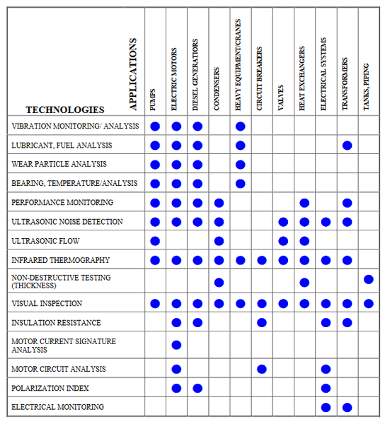
The following table provides an index of commonly available PT&I to common facilities components for which it can be applied. This info can be found in the NASA RCM Guide for Facilities and Collateral Equipment 5

Fig. 1. Commonly Available PT&I to Facility Components
Application
A. Acceptance Testing
A best practice use of PT&I technologies is in acceptance testing during construction and during the commissioning process.6 During the course of new construction, major repair, or rehabilitation of facilities, it is not unusual to discover installed systems or equipment that are out of alignment and balance, that contain latent defects from manufacturing and installation, or that simply do not operate as intended. For example, evaluations of new construction at two NASA Centers revealed that 85- to 100-percent of the rotating equipment was misaligned, out-of-balance, or contained defective bearings. These types of systems or equipment defects result in premature failures, which require unbudgeted corrective action by O&M staff. NASA employs an acceptance process that includes the use of PT&I to verify system and equipment condition. The acceptance process with PT&I can achieve results by:
- Ensuring there are no latent factory or installation defects
- Verifying building systems and equipment performance through functional performance testing
- Providing full documentation and training for the O&M staff to improve their performance
B. Operations & Maintenance (O&M)
Following acceptance of a facility it is placed in service to perform the functions for which it was acquired and is turned over to an O&M organization to maintain for its life. PT&I (predictive maintenance or condition monitoring) is one approach used in a modern O&M organization to maintain facilities during its operational phase. It does not lend itself to all types of equipment or possible failure modes and therefore should not be the sole type of maintenance practiced.
Additional Resources
Organizations
- American National Standards Institute
- American Petroleum Institute
- American Society of Mechanical Engineers
- American Society for Nondestructive Testing
- ASQ (American Society for Quality)
- ASTM International
- IEEE (Institute of Electrical and Electronics Engineers)
- Society for Maintenance and Reliability Professionals (SMRP)
- Vibration Institute
Publications
- Bannister, Kenneth E., Lubrication for Industry, Industrial Press, 0-8311-3061-X
- CSI, Data Collection Techniques, CSI
- Maintenance Technology magazine
- Mobley, R. Keith, Vibration Fundamentals, Butterworth Heinemann, 0-7506-7150-5
- Moubray, John, Reliability Centered Maintenance, 1997, Industrial Press, Inc., New York, ISBN: 0-8311-3078-4
- Plant Services magazine
- Reliabilityweb.com
- Reeves, Charles M., The Vibration Monitoring Handbook, Coxmoor Publishing Company, 1-90189-200-X
- Roylance and Hunt, Wear Debris Analysis, Coxmoor Publishing Company, 1-90189-202-6
- Thomas, Roderick A., Thermography, Coxmoor Publishing, 1-90189-201-8
- Toms, Larry, Machinery Oil Analysis, Coastal Skills Training
- Traister, John E., Handbook of Electric Motors: Use and Repair, PennWell Publishing Co., 0-87814-645-1
Footnotes
1 [Mitchell, John, et.al., "The Penn State Handbook – Operating Equipment Asset Management –Your 21st Century Competitive Necessity" October 1999.]
2 [MARCON 99 – Maintenance And Reliability Conference Proceedings, D. Walker, C. Mitchell, and R. Montgomery, "Reliability Centered Design: Inherently More Reliable Processes Through Superior Engineering Design" (May 10-12, 1999, College of Engineering, University of Tennessee).]
3 [Kenneth S. Jacobs, "Applying RCM Principles in the Selection of CBM-Enabling Technologies," ASNE, October 1999.]
4 [ANSI/ASNT CP-189-2001, American National Standards Institute/American Society for Non-Destructive Testing, 2001 Edition – ASNT Standard for Qualification and Certification of Nondestructive Testing Personnel.]
5 [NASA, "Reliability Centered Maintenance (RCM) Guide for Facilities and Collateral Equipment", March 2000.]
6 [NASA, "Reliability Centered Building and Equipment Acceptance (RCB&EA) Guide", February 2001.]


