Introduction
Within This Page
Electromagnetic pulses (EMP) from nuclear weapon detonations at altitudes from 30 to 400 kilometers (18 to 50 miles) can damage or destroy sensitive electronic equipment at ground level. High-altitude EMP (HEMP) has the potential to seriously disrupt commercial and military communications, damage the electrical grid infrastructure, and interfere with command and control operations. These disruptions can adversely affect federal, state, or local agency missions and operations.
The effects of HEMP span a wide frequency range (very low frequency to a few hundred megahertz [MHz]), and encompass critical commercial and military frequency bands. HEMP effects also produce damaging currents within power transmission, distribution, and communications lines resembling effects of geomagnetic disturbances or storms (e.g., solar flares). These disturbances can damage or destroy both electronic control equipment and the power transformers associated with electric grid distribution. Protection from HEMP effects is, therefore, essential.
This Resource Page provides guidelines for mitigating HEMP effects and reducing the associated risks to DoD missions. A basic understanding of HEMP and its effects, as well as specific mitigation technologies and strategies, are presented. These strategies are recommended as best practices to maximize effectiveness while minimizing cost of implementation. Recommendations to include requirements for HEMP protection in military contracts are also discussed.
Description
Characteristics of the High Altitude Electromagnetic Pulse (HEMP)
HEMP produced by a high altitude nuclear detonation exhibits three distinct phases created by the radiation and charged particles interacting with the atmosphere and the Earth's magnetic field. Each of these phases—E1, E2, and E3 (see image below)—has distinct characteristics and effects which can be mitigated with different methods.
The E1 (Early-time) phase, produces a very high-intensity pulse over a large frequency bandwidth of extremely short duration - nanoseconds to microseconds. It is produced by radiation from the nuclear blast interacting with specific layers in the atmosphere. This pulse propagates a blast wave along lines feeding communication equipment; direct absorption of energy induces high voltages and currents. Each effect may seriously damage electronics and electrical and communication systems.
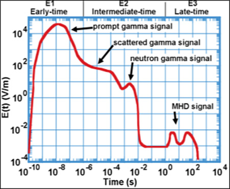
Three distinct phases created by radiation and charged particles.
The E2 (Intermediate-time) phase is also a product of radiation interacting with the atmosphere, but has characteristics closely resembling the effects created by lightning strikes, lasting from microseconds to seconds. These "induction effects" differ from actual lightning in that there is no current surge produced directly as would be the case of a bolt of lightning striking an electric pole or a house. E2 induction effects resemble and are equivalent to the electromagnetic pulse that radiates from a lightning bolt that impinges during a discharge on sensitive electronics and equipment.
E3 (Late-time) is produced by the slow movement of charged particles within the heated plasma fireball from the nuclear blast as it interacts with the Earth's magnetic field. Effects of this phase last from seconds to minutes. The blast expands as it moves through the atmosphere, then lifts upward. E3 effects are very similar to those produced by solar flares, but they can be significantly more intense. They result in large current surges on the order of hundreds to thousands of amperes produced at ground level that couple onto power lines and communications lines through induction. These current surges produce various adverse effects, particularly to power lines, damaging equipment and transformers by overheating the transformer core and windings.
An Overall Approach to HEMP Mitigation
The combined effects of HEMP require different technologies and methods for mitigation. Fortunately, there has been significant research and development conducted that have produced many viable solutions to provide effective protection.
Providing protection against HEMP is a process-based approach that combines the application of various technologies with appropriate tactics, techniques, and procedures. Various technology options are available to provide physical protection against the three phases of HEMP; but just as important are the methods and approaches used to apply these technologies.
In general, options for mitigation source three technologies: electromagnetic shielding; HEMP special filtering; and surge protection (see illustration below). Additionally, proper grounding, and, in some instances, electrical isolation, can offer improved protection against HEMP effects.
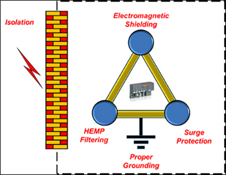
Technologies that mitigate against HEMP effects.
Electromagnetic Shielding
Electromagnetic shielding provides excellent protection against direct absorption effects (i.e., electromagnetic waves impinging directly onto equipment) of the E1 and E2 phases of HEMP. Various metals and other materials with differing weights, sizes, and costs can provide very high levels of electromagnetic wave attenuation to protect equipment. The material selected ties directly to the level of protection needed and the infrastructure to be protected. Shielding can be incorporated in both new construction and renovations, and for whole structures or within specific areas or rooms, or even individual equipment items.
The most common shielding method uses metal containers and boxes, and is particularly suitable for small equipment. The most common metal employed in shielding is copper. However, other metals can be used such as aluminum or steel. In special instances, more exotic metals, such as ferromagnetic alloy metals, are used, particularly when magnetic effects come into play.
Larger areas or whole buildings may be shielded with metal sheeting, or metal foils and conductive paints can be used. Additionally, emerging technologies such as electrically conductive concretes are increasingly attracting attention. In these cases, cost must be weighed against the desired level of protection.
Special HEMP Filtering
HEMP filtering addresses the E1 phase. As indicated, E1 effects can be both directly coupled into equipment and injected as induced currents.
For military applications, special HEMP filtering technology meeting the stringent requirements of the Department of Defense Interface Standard MIL STD 188/125, High-Altitude Electromagnetic Pulse (HEMP) Protection for Ground-based C4I Facilities Performing Critical Time-Urgent Missions, Part 1 and Part 2, and MIL-STD-464C, Electromagnetic Environmental Effects Requirements for Systems are usually selected. The purpose of HEMP filtering is to prevent or "arrest" induction surge created by the HEMP pulse from coupling into sensitive equipment. While filtering specifications are extensive, capabilities typically include very high-surge Pulse Current Injection (PCI) protection and very fast rise-time response.
Surge Protection
Particularly useful to mitigate E2 phase effects, surge protection technologies prevent damage to electronics and electrical systems from induced currents in lines. Surge protection technologies are well-established and are a standard for lightning protection. Generally, these technologies are variants on Metal-Oxide-Varistors (MOV) or Transient Voltage Suppression (TVS) diodes (also known as avalanche diodes). Other devices such as thyristor protection or gas discharge tubes are also used.
These devices limit a high voltage surge that exceeds a preset limit by shunting or blocking the current flow from being introduced into electronic or electrical systems. Their many configurations range from simple home surge protection strips to larger whole-home or building protection. It must be noted that these devices protect against induced current/voltage transients (HEMP E2 or a nearby lightning strike), not direct lightning strike to an ingress/egress power or communication line.
Additional Techniques
Two common techniques applied to electrical and electronic systems to improve resilience against HEMP effects are grounding and isolation. Both limit exposure to HEMP-generated effects, but they differ in that they are electrical configuration techniques, as opposed to applied devices or material solutions.
Other techniques to provide HEMP protection include reliance on natural shielding provided by facility infrastructure or the application of beyond cutoff waveguides for points of entry into structures.
Grounding
Grounding is not a stand-alone solution for HEMP protection; but proper grounding provides a baseline that supports additional protection measures. Mitigation options such as shielding and shunting technologies require proper ground to be effective. Several key functions of grounding are important in HEMP protection. First, it is essential to maintain the lowest possible potential difference along the ground—particularly for long lines—to provide a stable equipotential ground for the entire system. In addition, the ground system should be designed to provide an adequate surge current sink without significantly raising the ground potential locally. Best practices for proper grounding are provided in several standards, including MIL-STD-188/125, Part 1 and Part 2, and should be consulted for more information on grounding requirements.
Isolation
As with grounding, electrical isolation may involve many options. However, the overarching goal is to prevent or reduce induction of HEMP-produced currents from entering sensitive systems. An area where isolation is particularly effective is in mitigation of the extremely low frequency components of E3-induced currents. As indicated, these currents are very similar to those produced by solar flares and geomagnetic sun spot storms, but with significantly more serious impact.
These are very slow time-varying currents, almost a direct current effect, and they are particularly troublesome for transformers and power lines. One example is the induction of these currents onto the neutral line of a standard configured distribution transformer system which can couple directly into the facility ground system. Currents introduced into the long transmission and distribution lines can cause serious heating in the transformers and propagate harmonic generation issues downstream that can seriously affect other equipment.
A typical mitigation method for this effect is to configure transformers to block the E3 effects from entering the facility. Another method is to insert blocking capacitors and shunt devices into the distribution lines to block the E3-induced currents before they get to the facility distribution points. A third method is to allow the infrastructure ground to be disconnected from earth ground for isolation.
Overall HEMP Resilience: Tactics, Techniques, and Procedures for HEMP Event Survival
A more comprehensive approach to HEMP protection involves resilience, which addresses the entire timeline of a HEMP event, from the pre-planning stage through post-event recovery. Resilience must address infrastructure robustness, such as the protections already described, as well as other tactics and techniques. These may include redundancies in capability; resourcefulness and out-of-the-box thinking to identify novel means to overcome HEMP effects; and the ability to respond with necessary manpower and equipment to affect efficient recovery.
Appropriate Redundancy
Redundancy—particularly with respect to critical equipment—can provide a level of resilience against HEMP effects. However, having spares or backups is only a part of effective redundancy: the redundancy must be at least as robust in resisting HEMP effects as the capability it is backing up. For example, procuring extra power system control equipment only provides reliable redundancy if the backups are themselves protected from HEMP effects. This could be achieved with shielded storage or dispersal and relocation of equipment to areas less likely to be affected by HEMP.
Dispersal and Relocation
Securing assets via dispersal and relocation, as with the EMP Protection-in-a-Box concept, can provide protection against HEMP effects. This strategy dilutes risk by moving critical assets to more secure locations, or providing HEMP protection for those assets only.
Resourcefulness
Resourcefulness as a HEMP protective tactic involves creative thinking. For example, if base infrastructure is severely affected, can nearby community capability that is still functioning be borrowed or leased? Can the commercial sector substitute for damaged capability in a timely manner? Is it possible to implement "Rube Goldberg" solutions to restore critical capability to a workable level? Key to resourcefulness is situational awareness regarding what is available for support and maintaining an open mind to identify options that would not be considered during normal day-to-day operations.
Planning for Recovery
If a HEMP event occurs, there will be adverse effects. Rapid recovery is key to resilience. Keys to rapid recovery are the qualified personnel and other resources to implement repairs. Rapid recovery also requires recovery plans and procedures for executing those plans. Recovery is an incremental process; pre-planning and identifying the most critical infrastructure to recover first is essential. Recovery also requires an intimate understanding of the base infrastructure and its mission; personnel executing recovery should have prior knowledge of the base sufficient to provide the most effective and efficient recovery actions.
Protection In-Depth
The concept of Protection-In-Depth (PID) employs multiple layers or schemes to provide hardening and mitigation against HEMP effects. This tactic is particularly useful when applying electromagnetic shielding protection. Schemes can involve the enclosing infrastructure itself, which can provide a certain level of hardening. For example, a concrete and rebar structure that provides an inherent level of shielding may be combined with interior walls fitted with metal foils and/or conductive paints. Adding electromagnetic shielded cases or enclosures for specific equipment can provide a complete protection solution. Layered concepts provide very effective shielding, and in many cases, offer significant cost savings over implementing a fully shielded building enclosure.
Planning Prior to Acquisition of Capability
The Air Force uses several methods and vehicles to acquire energy services and support. These include the Energy Savings Performance Contracts (ESPC), Energy Service ContractsDownload Consolidated_UESC_Final_2019.pdf (UESC), military construction for energy projects through the Energy Resilience and Conservation Investment Program (ERCIP), and a host of other government-utility and private sector arrangements. Prudent planners should include HEMP protection in the requirements of these acquisition vehicles. Under many of these programs, the private sector assumes a significant level of the HEMP risk to the infrastructure/capabilities that will be provided to the Air Force; including protection in these acquisitions will ensure the Air Force mission is assured following a HEMP event. Air Force installation commanders should review AFI 10-2607, Chemical, Biological, Radiological, and Nuclear Survivability , when determining mission criticality and protection.
Emerging Protection Capability: The "EMP-in-a-Box" Concept
A new concept, known as "EMP-in-a-Box," provides expedient, mobile, and expeditionary protection in a self-contained, scalable, modular design that is suitable for specialized applications.
Application
Most HEMP solutions are tailored to a specific application: remote or mobile Sensitive Compartmented Information Facilities (SCIF); relocated missions like command and control; special equipment like computers, servers, or communications equipment; or backup energy sources such as batteries or generators. "EMP-in-a-Box" provides a complete solution to HEMP protection in a single package.
The "EMP-in-a-Box" advantage relies upon small, modular components with rapid install. Manpower and toolset requirements are minimal. These attributes allow for scaling that support varying missions, including expedient and expeditionary applications, and flexibility to re-scale in parallel with mission requirements.
Key components are the same as components for custom retrofit or new construction specified by MIL-STD-188/125, Part 1 and Part 2. As a standalone implementation, "EMP-in-a-Box" mitigates only E1 and E2 effects. Because E3 influences primarily the long lines entering into the "EMP in a Box," additional HEMP protection external to the "EMP-in-a-Box" is required. (A typical configuration is shown below.)
Note: There are other methods and techniques for HEMP E3 protection; those discussed in this Resource Page illustrate the key aspects of protection. Enclosures must be continuous against penetration, ingress/egress must be managed, and isolation from externally induced effects is critical to provide overall protection. Following these underlying principles will provide protection against the effects of a HEMP event.
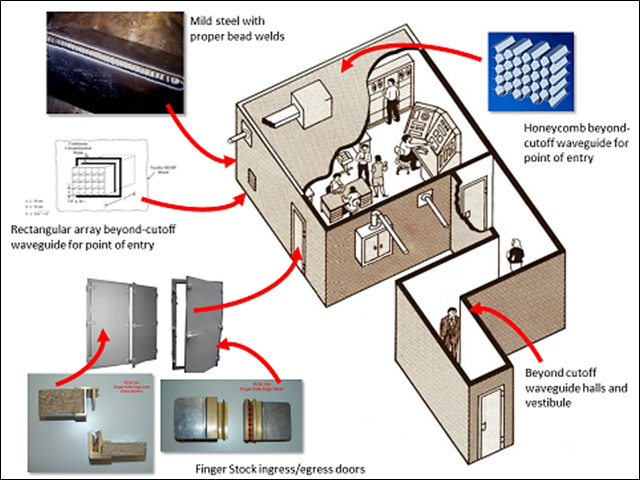
A typical "EMP-in-a-Box" configuration.
Addressing E1 and E2 with "EMP-in-a-Box"
HEMP E1 and E2 phases involve direct illumination and induced currents from the higher frequency components of electromagnetic radiation. Shielded walls and surfaces are the principal components of E1 and E2 mitigation. Mild steel plate is commonly used. Steel provides very good shielding across a large frequency band and, because of its ferromagnetic properties, is effective at lower frequencies where magnetic fields are problematic. A key aspect of effective shielding is joining surfaces via welding. Welding ensures the minimum 80 dB attenuation across the bands required by MIL-STD-188/125 . Welding beads must be continuous along seams. Foreign objects and pinhole gaps must be excluded—debris can introduce localized resistance and degrade performance; gaps and pinholes provide entry points for electromagnetic radiation, particularly at higher frequencies.
Points of entry for electrical power and communications connections are critical. The source of the line (such as from a shielded generator to the building it is supplying) can be completely shielded, creating a continuous shielded enclosure around all components. Unfortunately, this can be cumbersome and expensive. An alternative is to apply waveguides beyond cutoffs at openings into the shielded area (such as for ventilation and piping). This technique effectively blocks electromagnetic (EM) wave transmission by ensuring that the physical geometry of the waveguide opening will not support travelling wave propagation. A third option is to apply beyond cutoff waveguides as ingress/egress for fiber optic cable (not susceptible to EM coupling). Converting signals to transit fiber optic cable eliminates HEMP-induced currents.
Doors used for traffic into and out of a shielded area introduce special vulnerability. Complete seal with welds is impossible, making special door systems necessary. There are various options, each with different levels of attenuation. Most common are finger stock door systems, which use a blade and metallic finger stock ribbon insert to ensure electromagnetic shield continuity. These door systems are combined with dual-door vestibules to ensure the protected area is always enclosed, and typically have beyond cutoff waveguides installed as the door hallways.
Heating, ventilation, and air-conditioning (HVAC) systems that are critical to maintaining environmental control within enclosures, including "EMP-in-a-box" concepts must be addressed. Attention to ingress/egress points of entry for HVAC systems should be protected to prevent E1 and E2 electromagnetic leakage into protected areas. The same beyond cutoff waveguide techniques can be applied to HVAC systems. Additionally, special precautions, such as those applied to other powered systems (e.g. generators) to prevent damage to electronic and electrical systems associated with HVAC systems, should be implemented.
Other options for mitigating mid-range frequency effects from the E2 portion of a HEMP event are readily available. As E2 closely resembles the frequency components of lightning induced effects, surge suppression components are very effective. They are particularly useful for incoming power lines, and as added protection internal to the shielded area.
Addressing E3 with Additions to "EMP-in-a-Box"
Effective enclosure and maintaining shield integrity at points of entry is only one aspect of HEMP effects mitigation. Other approaches must be applied—in particular, to long lines feeding power to buildings and enclosures—to mitigate E3 effects. These power lines can stretch very long distances, and the induced very-low frequency currents—almost direct current in nature—magnify and can cause severe damage to power conversion and control systems, especially motors and transformers.
E3 mitigation is generally ancillary to "EMP-in-a-Box"; it is added to provide E3 protection outside of the "EMP-in-a-Box" enclosure. Two technologies are commonly used: direct current blocking/very low frequency, high pass filtering (e.g., capacitors); and combining delta-wye transformers to provide isolation, particularly for ground lines.
Capacitor and filter options (as well as fast-blow fuses) provide a block or shunt to the induced near-DC currents on long power transmission and distribution lines. This approach can also be applied to long-haul communications lines such as telephone and cable lines. As already noted, conversion of communication lines to fiber optic, before entry into the protected area, is effective. For power lines, use of Delta-Wye configured transformers to isolate the distribution ground from the building or enclosure ground is more common (illustrated below).
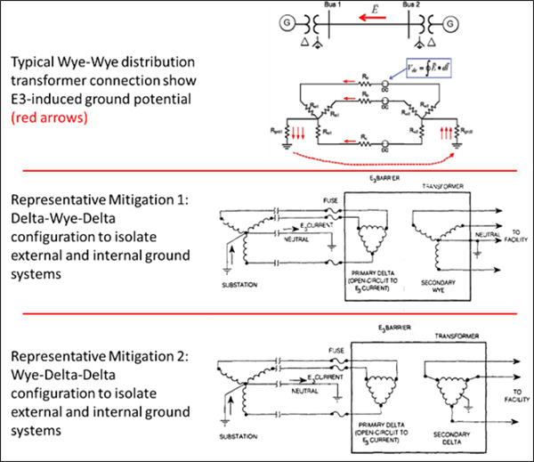
Use of Delta-Wye configured transformers to isolate the distribution ground from the building or enclosure ground is more common in power lines.
In direct connected Wye-to-Wye transformers for distribution lines, near-DC currents are induced in the separate phases and these contribute to raising the voltage potential of the common ground. If this ground then is connected to the ground for the protected area, it too will experience a rise in DC potential. This can be very damaging to equipment transformers as the DC component will skew the magnetic properties of the transformer core and cause severe localized heating. This can cause windings to burn out, or even the core to experience localized melting, both of which will destroy the transformer.
To eliminate this ground potential change from entering a protected area and its associated ground plane, the Delta-Wye (or Wye-Delta) configuration is inserted, effectively isolating the two different ground systems. Note, however, the trend under privatization of the electrical distribution on installations is to use Wye-Wye distribution transformer configurations to increase current carrying capacity to handle more load at reduced cost. This increases vulnerability to E3 HEMP effects, as depicted in the top portion of the illustration above.
Example: Modular EMP Retrofit
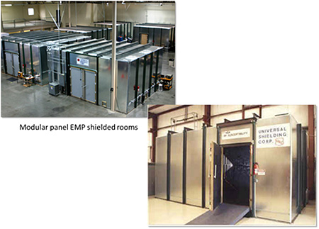
A common application of EMP protection is to apply retrofit to existing infrastructure. This can range from small, special function or mission critical areas (such as command and control), to entire buildings. In these cases, the key to "EMP-in-a-Box" lies in modular solutions that can be packaged and shipped to location for retrofitting. Solutions typically consist of standard-sized components, such as wall panels and ceiling/floor kits, and associated ingress/egress door systems. Standard support components, such as beyond cutoff wave guides for cables, fiber optic conversion kits for communications, and computing and possible retrofit kits for power filtering and conditioning, are included. (A representative protective construct is shown below.)
Example: Transportable Enclosure for Command and Control
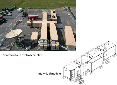
Transportable and modular EMP protective systems often find application in forward operating locations for mission critical functions like command, control, and communications. These systems offer the advantage of self-containment and standard transportability while allowing for the use of multiple modules to accommodate customized mission requirements. This flexibility also allows for expansion or reduction in size and capability based on changing mission requirements. (A representative system is shown below.)
Example: EMP-protected Power Generation
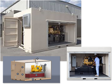
Power generation is a critical component supporting all missions. For backup and emergency power, the most common source for electricity is fuel-driven generators. During critical events, such as a HEMP event, it is crucial that backup generators survive in order to keep other mission critical functions operating. Commercially available products exist that provide EMP protection in self-contained and modular configurations. These products provide HEMP protection for the generator and its control systems, as well as provide HEMP-mitigated ingress/egress for fueling, exhaust, and electrical and control cabling. These systems support easy access for generator maintenance and repair and their modularity supports custom configuration for multiple generators. (A typical system is shown below.)
Example: Air Force AFIMSC "EMP-in-a-Box" Solution
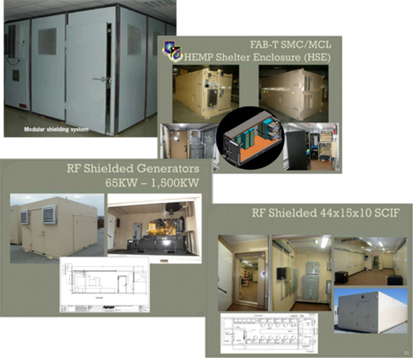
The United States Air Force Air Force Installation and Mission Support Center (AFIMSC) has developed four "EMP-in-a-Box" solutions that provide protection to Air Force Mission and infrastructure similar to the examples provided above. The AFIMSC solutions incorporate modularity and scalability that allow mission owners to tailor HEMP mitigation to most effectively support critical missions. The solutions provide protection for single units or components and are expandable to support multiple units and areas. Additionally, the solutions are tailorable to address specialized missions up to the full facility level. (Two examples are shown below.)
Maintenance and Life-Cycle Management
All systems degrade over time and EMP protective systems are no exception. Exposure to the elements can rapidly degrade the quality and effectiveness of EMP protective systems. Normal use, wear-and-tear also degrades performance over time. Additionally, damage to the protected equipment/area can severely reduce the effectiveness of its EMP protective system. These issues must be addressed during the life cycle of the system to ensure that critical components and the missions they support are continuously and effectively protected. Regular maintenance, coupled with regular performance monitoring, is key.
System Degradation from the Elements
The primary adverse effect to EMP systems from exposure to the elements is corrosion. This can be particularly acute in high saltwater environments. Corrosion (a.k.a., "rust") decreases the surface conductivity of metal enclosures, which in turn reduces their capability to attenuate electromagnetic radiation. Corrosion can also eventually cause pinholes and cracks to form in the continuous metal skin that is key to proper EMP shielding. Further, corrosion to ingress/egress beyond cutoff waveguides can reduce or even eliminate their effectiveness.
Corrosion preventionDownload afi_32_1054.pdf begins with initial installation. Use of proper coatings and paints to prevent corrosion is a critical part of life-cycle maintenance. Regular inspection of paints and coatings, as well as inspection for below-coating corrosion, are necessary parts of the regular maintenance cycle.
Wear and Tear
Normal use of an EMP system induces wear and tear to system components, particularly doors and entryways. Most systems employ interleave schemes such as finger stock, blade-and-sheath systems to provide EMP attenuation. These can wear such that tight connections no longer exist or they can be damaged such that gaps are created. Regular inspection and replacement—especially in high traffic areas—are very important to maintaining system integrity.
EM radiation-absorbing gaskets are another component that requires regular inspection and replacement. As these wear either from use or age they can degrade attenuation performance of the system.
Physical Damage
Physical damage to HEMP protection is most commonly a shield breach from a puncture or tear, and usually accidental. Care must be exercised when working close to the system, either inside or outside. A forklift or equipment mover can easily puncture or tear a wall section. Accidental drilling can also damage the integrity of the system.
Testing, Monitoring, Mitigation
To maintain EMP protective systems, testing and continuous monitoring of the systems are required. Regular EM testing, such as measuring the attenuation inside of the protected area and applying pulsed current injection testing to measure performance against surges, is necessary. This not only provides a measure of life-cycle degradation, but also helps to determine the regular maintenance schedule to maintain performance over time.
Newer systems include embedded sensing, usually antenna systems, that allow continuous monitoring of overall performance. Such monitoring can also help isolate the location of any system degradation.
Many systems employ built-in headroom to extend the time to maintenance and repair. Generally, this is accomplished by over-designing the protection attenuation level by 20 to 40 decibels over the requirement. This increases the time period of degradation to minimal protection levels, also lowering costs by increasing the time intervals between maintenance cycles.
Conclusion
The effects of a HEMP event can severely degrade or destroy the electronic and electrical systems critical to mission support. The broad frequency ranges and the high intensity fields can enter systems through direct coupling and as induced pulsed current surge that can quickly render missions ineffective or inoperable. A suite of solutions exists that provide extremely effective protection to mission-critical infrastructure. These solutions are well understood, commercially available, and support both fixed location and expedient and expeditionary sites. They can be implemented in new construction; as larger-scale retrofits to existing infrastructure; or as small, mobile systems using modular and expandable solutions to support changing mission needs.
Implementing HEMP protection requires planning based on the mission, and should take advantage of the principles of overall resiliency. Solutions should include not only the technology, but apply to pre-planning, redundancy, and novel thinking.
HEMP solutions must be maintained over the life cycle of the system to ensure the Air Force mission is protected. This includes regular inspection and maintenance, as well as planning for upgrades as newer, more effective technology is developed.
Relevant Codes, Standards, and Guidelines
- Air Force Instruction (AFI) 10-2607, Chemical, Biological, Radiological, and Nuclear SurvivabilityDownload afi10-2607.pdf , August 9, 2018.
- Executive Order 13865, Coordinating National Resilience to Electromagnetic Pulses, March 26, 2019.
- MIL-STD-188/125-1, Department of Defense Interface Standard: High Altitude Electromagnetic Pulse (HEMP) Protection for Ground-based C4I Facilities Performing Critical, Time-Urgent Missions, (Part 1 - Fixed Facilities).
- MIL-STD-188/125-2, Department of Defense Interface Standard: High-Altitude Electromagnetic Pulse (HEMP) Protection for Ground-Based C4i Facilities Performing Critical, Time-Urgent Missions, (Part 2 - Transportable Systems).
- MIL-STD-461G, Military Standard: Electromagnetic Interference Characteristics Requirements for Equipment.
- MIL-STD-464C, Department of Defense Interface Standard: Electromagnetic Environmental Effects Requirements for Systems.
- Rescind RPIE Determination Memo, October 25, 1989, Subject HEMP/TEMPEST Shielding in Facilities (Your Ltr, August 1, 1989), MEMORANDUM FOR AFCEC/CIT from HQ USAF/A4CA, Dec 19, 2018.
Additional Resources
Publications
- Electromagnetic Pulse (EMP) Protection and Restoration Guidelines for Equipment and Facilities with Appendices A-CDownload DHSEMPRec.pdf by the Department of Homeland Security, National Coordinating Center for Communications (NCC), National Cybersecurity and Communications Integration Center (NCCIC). Arlington VA: Dec 22, 2016.
- "High Altitude Electromagnetic Pulse (HEMP) Impacts on the Grid"Download Overbye_EMPb_June2016.pdf Power Systems Engineering Research Center (PSERC) Tutorial by Thomas J. Overbye. University of Illinois at Urbana-Champaign, E-Mail: overbye@illinois.edu, June 8, 2016.
- Metatech Report Meta-R-320, The Early-Time (E1) High-Altitude Electromagnetic Pulse (HEMP) and Its Impact on the U.S. Power GridDownload meta-r-320.pdf
- Mitigation of Magnetohydrodynamic Electromagnetic Pulse: Effects from Commercial Electric Power Systems by P. R. Barnes, F. M. Tesche, E. F. Vance. Oak Ridge National Laboratory, ONRL-6709, AD 249577, May 4, 1992.
- "Nuclear Enterprise EMP Protection Issues and Challenges" by Mr. Russell Weniger. AFIMSC/IZBO, Apr 19, 2019.
Other
- Aluminum Weld Repair Video
- EMP Shielded Generator Enclosures, Armag Corporation, 300 Armag Avenue, Bardstown, KY 40004.
- Faraday Cage Doors
- HEMP: Transportable Enclosures, EMP Engineering, 607 Lynnhaven Parkway, Virginia Beach, VA 23452, E-Mail: info@hardenedstructures.com, Toll Free: +1 (877) 486-0084.
- RF Shielded Doors
- Standard RF Shielded Rooms, Universal Shielding Corporation USC-26 room; RF Shielded Rooms—Solid Wall R. A. Mayes Company, Inc., An Electro Mechanical Research and Development (EMRAD) Corporation, Company, Copyright © 2001-2020.


