Introduction
Within This Page
- Introduction
- Description
- Application
- Operations and Maintenance
- Special Considerations
- Relevant Codes and Standards
- Additional Resources
THIS PAGE SUPPORTED BY THE
![]()
Commercially available since the 1970s, photovoltaic (PV) technology converts energy from solar radiation directly into electricity using semiconductor materials. It has no mechanical moving parts and lasts for decades while requiring only minimal periodic maintenance. Applications range from small-scale projects for individual groups of lighting fixtures and water pumps, to larger-scale projects for whole building power supplies, to community-scale solar gardens that service hundreds of consumers, to utility-scale photovoltaic power plants that provide electricity to thousands of end-users.
Advantages of site-based photovoltaic systems are that they can be located directly at the point of power consumption, offset the full retail electricity rate of the facility, and match the peak demand loads of the end user. They are modular and can be installed on any unobstructed roof or ground space. Community solar and utility-scale installations provide a clean energy source for thousands of consumers who may wish to lower their carbon footprint but have project sites that are not ideal for solar installations. Photovoltaic technology often qualifies for more financial incentives than other renewable energy technologies. For example, in states that have a "solar set-aside" in their renewable energy requirements, the renewable energy certificates can be much higher than those provided for other technologies.
This overview is intended to provide specific details for Federal agencies considering photovoltaic technologies as part of a new construction project or major renovation. Further general information is available from the U.S. Department of Energy (DOE) Office of Energy Efficiency and Renewable Energy (EERE) Photovoltaics Technology Basics.
Description
System Overview
Photovoltaic systems are made up of several major components including:
- PV Modules, and
- Balance of System (BOS) Components
- Module Mounting Systems
- Wiring, Combiner Boxes, DC Disconnects, AC Disconnects
- Inverters (and Transformers for larger systems)
- Electrical Distribution Panels
- Batteries
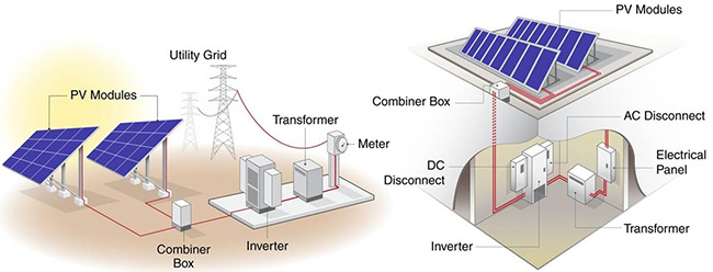
Typical grid-connected photovoltaic systems, utility-scale (left) and commercial roof-top (right)
Source: U.S. Department of Energy, EERE
Modules
The most recognizable component of a PV system is the rectangular solar collector module. Traditional PV modules are an assembly of individual wafer cells arranged in a rectilinear pattern, wired together, and encased in a rigid frame. Each module has an attached positive and negative connector cable on the back side which allows adjacent modules to be joined together. Photovoltaic modules come in a wide variety of types and sizes which enables a photovoltaic system to be designed to best match the available installation space, the environmental conditions, the electrical generation requirements, and the financial budget of the project. Modules for residential and commercial-scale projects are usually about 40" by 66" in size, but for utility-scale projects they can be much larger, with dimensions up to 52" wide and 97" long.
Modules vary by the type of PV technology being used, how the cells are wired together, and the characteristics of the module encasement. Some modules perform better in low-light conditions, while others can generate larger amounts of power in high-intensity direct sunlight. All modules generate direct current (DC) electricity, which can then be converted into alternating current (AC) using an inverter. Modules are given power output ratings based on tested performance at the industry's standard test conditions (STC). This information is printed on data labels located on the back of the modules. Most photovoltaic modules have 25–year warranties for defects and system performance. A typical performance warranty guarantees that the module will produce a minimum of 85% of its rated power for at least 25 years.
Balance of System (BOS)
The term "Balance of System" (BOS) refers to everything in a PV system other than the modules themselves. This includes the mounting system, wiring, combiner boxes, switches / disconnects, inverters, meters, batteries, and so on. Common types of mounting systems used to secure PV modules in place are metal frameworks called "racking." These systems can be directly attached to a roof, the ground, or another structure. Roof-top racking systems can also utilize weights (ballast) to hold the modules in place without requiring any roof penetrations. Mounting racks, like all building structures, must withstand wind loads in the 90 to 110 mph range for most areas or as high as 150+ mph for areas with hurricane potential.
Multiple modules can be connected together to create "strings," which are then joined to create an array. The modules can be connected in series or in parallel as needed to reach the specific voltage and current requirements for the array. Combiner boxes are used to combine the electrical cables from multiple strings into a single cable that connects to the inverter. Combiner boxes provide over-current protection and reduce the overall amount of system wiring.
An inverter converts the direct current (DC) electricity from the array into an alternating current (AC) that can be used for local power loads, fed to a micro-grid, or supplied to the larger utility grid. DC to AC conversion efficiencies are typically at least 98%. The inverter also senses the utility power frequency and synchronizes the photovoltaic-produced power to that frequency. When utility power is not present, such as during blackouts, the inverter will stop producing AC power for safety reasons. This prevents "islanding," which refers to putting power into the grid while it is de-energized. This is to protect the utility workers from electrical injuries while they are repairing the grid infrastructure. The anti-islanding feature is built into all grid-connected inverters on the market. In addition, the NEC 690.12 Rapid Shutdown of PV Systems on Buildings code requirement states that PV modules are to be mounted with devices to reduce or eliminate power output within seconds when triggered. All conductors within a 1–ft boundary of an array have to be reduced to 80 volts or less (or 30 volts or less depending on specific conditions) within 30 seconds of rapid shutdown initiation. This rule is intended to protect firefighters and first responders that may come in close contact to a roof-top PV array. An easily accessible and readily identifiable switch on the building exterior is used to communicate with module mounted devices to initiate the shutdown.1
There are two primary types of inverters for grid-connected systems: string and micro-inverters. Each has strengths and weakness that help determine the most appropriate fit for an installation. String inverters handle the output from multiple modules, whereas micro-inverters are dedicated to a single module.
String inverters typically range in size from 1.5 kW to 500 kW. Benefits of these inverters are that they tend to be less expensive per watt of capacity and provide a large range of output voltages. On the downside, if the inverter goes down, a significant part of production could be lost during the outage. For larger photovoltaic systems, these inverters can be combined in parallel to produce a single point of interconnection with the grid. Warranties are available for all sizes and typically run between 5 to 10 years, with 10 years being the current industry standard. On larger inverters, extended warranties of up to 20 or 25 years may be available for additional cost. It is expected that the inverter will be replaced one time during the life of the photovoltaic system. Power Optimizers are module-attached components used with string inverters. They maximize the DC power output for an individual module based on fluctuating environmental conditions such as sunlight levels and temperature changes.
Micro-inverters are dedicated to the conversion of a single photovoltaic module's power output from DC to AC and are attached to the module. The resultant AC output from each module is connected in parallel to create the array. Micro-inverters range in size from 175 watts to 380 watts. Warranties range from 10 to 25 years. Smaller projects with irregular modules and shading issues typically benefit from micro-inverters. Micro-inverters work well with system monitoring software because the power output from each individual module can be continually assessed to determine if the module is functioning at the level intended.
The BOS also includes electrical panels and related equipment. All systems require switch gear and protections as specified by electrical code (e.g. NEC 690). These may be a few disconnect switches, fuses, or breakers; or possibly a transformer if it is a higher voltage interconnection.
In some instances, the photovoltaic system may also include battery storage. The power from the photovoltaic array keeps the batteries charged, and when needed the batteries provide the building with power if the grid is unavailable. While batteries add cost to a PV installation, their presence enables building operations to continue uninterrupted during grid power outages. Batteries don't necessarily have to be sized to support the entire building electrical load. They can also be designed to only supply power to critical circuits or high-priority equipment. Photovoltaic systems with battery storage include a charge controller, which could be separate or integrated into the inverter. The charge controller controls both the DC voltage that is coming from the photovoltaic array and the voltage going into the batteries. To help extend their longevity, batteries require specific stages of charging produced by charge controllers. Many manufacturers now provide self-contained inverter / battery storage units that can be installed "plug-and-play" fashion into a PV installation. Smaller systems can utilize integrated wall-mounted components, and larger installations can take advantage of modular, industrial container-sized units.
Real-time, monitoring software is also a common facet of an integrated PV system. Software programs can keep track of power production, conduct economic analyses, run diagnostics, and even distribute electricity for specific loads based on user-defined priorities.
How Does A Photovoltaic Cell Work?
PV cells generate electricity through the "photovoltaic effect." This process occurs when sunlight interacts with the materials within cells and electrons are released, which in turn become the electricity that flows within a circuit. Even though PV cells are manufactured with a variety of materials and may be wired together differently depending on the manufacturer and material technology, this photovoltaic effect is common to all cell types.
PV cells are manufactured out of semi-conductor materials. These are solid materials that conduct electricity under some conditions but not others. This is possible because there are certain electrons within these materials that are more easily elevated to higher energy levels, which in turn permit them to move more freely to neighboring atoms. The energy required to separate these electrons from their original nuclei is referred to as bandgap energy. In semi-conductors, this energy can come from light itself. Higher energy photons within sunlight colliding with semi-conductor atoms, can impart enough energy so that electrons are elevated to higher "conduction" energy levels. These electrons are then free to move to neighboring atoms.
When electrons are raised to a higher energy level, they leave behind a "hole." Electrons are negatively charged and holes are positively charged. When manufacturing semi-conductors, the initial wafer material is doped (subjected to processes that introduce small amounts of other materials) in order to increase the amount of excess negative electrons or positive holes. N-type semi-conductors have been doped so they have more electrons, P-type so they have more holes.
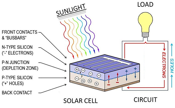
The photovoltaic effect occurs when energy in sunlight causes electrons in semi-conductors to be elevated into the conduction zone, where they are free to move as electricity in an external circuit.
Image: Ronald Fergle
When electrons move in one direction, the holes move in the other. When sunlight strikes the semi-conductor cell wafer and the electrons and holes migrate, they begin to concentrate on opposite sides of the wafer. They are not able to recombine because PV cells act as rectifying diodes. This means that they permit the negative and positive charges to each diffuse in only one direction. When connected to an external circuit, the build-up of negatively charged electrons will move through the circuit in order to return to the positively charged side of the cell (and, the positively charged holes will move in the opposite direction in order to rejoin the negatively charged side of the cell). PV cells are wired together to create modules, which are then connected to create strings. The accumulation of all the individual electron movement produces the overall electrical output of the array.
Types of PV Technology
The photovoltaic effect was discovered in 1839, but it wasn't until 1883 that the first solid state solar cell was created, with 1% efficiency. In 1954 the modern solar cell was developed, with 6% efficiency. Now, based on the type of PV technology used, researchers are achieving electrical output that would have been unimaginable only a few decades ago.
The primary photovoltaic cell categories include:
- Multijunction Cells and Single-Junction Gallium Arsenide (GaAs)
- Crystalline Silicon (Si) Cells
- Thin-Film Technologies
- Emerging PV
Multijunction Cells and Single-Junction Gallium Arsenide
These types of photovoltaic cells are the most efficient in terms of converting sunlight into electricity, with efficiencies exceeding 47% under concentrated sunlight. They are able to maximize the release of electrons by using multiple layers of semi-conductor materials with different band-gap energies to absorb different wavelengths of light. Instead of silicon (Si), they use gallium indium phosphide (GaInP), indium gallium arsenide (InGaAs), or germanium (Ge). They are expensive however, which limits their application to aerial drones, space exploration, and military uses.
Crystalline Silicon Cells
These photovoltaic cells are made from crystalline silicon (c-Si) wafers. Cell efficiencies can be as high as 27% in research laboratory settings and 24% in commercial versions. Circular wafers (later trimmed) are initially cut from long cylinders of mono-crystalline silicon, and square wafers are cut from large ingots of poly-crystalline (also called multi-crystalline) silicon. (Mono-crystalline provides slightly higher efficiencies but is more expensive than poly-crystalline.) These initial wafers are then polished and doped with elements such as boron (B) or phosphorus (P), and an anti-reflective (AR) coating is applied. Thin metal "busbar" contacts are then screened onto the surface for collecting the electrons released in the photovoltaic process. Most commercial modules use technology based on c-Si cells. Nano-technology and the application of additional semi-conductor layers continue to push the cell efficiencies higher.
Thin-Film Technologies
Thin-film technologies include copper indium gallium (di)selenide (CIGS), cadmium telluride (CdTe), and amorphous silicon (a-Si) cells. While laboratory efficiencies are around 23%, commercial versions are in excess of 19% for CIGS, 19% for CdTe, and 12% for a-Si.2 These types of cells are created using plasma enhanced chemical vapor deposition (PECVD) techniques. This is where thin layers of semi-conductor elements are deposited onto backing substrate materials in a vacuum chamber by using plasma of energetic electrons to ionize the reactant source gases. These cells have lower efficiency levels compared to c-Si wafers, but they can be manufactured quicker and they cost less.
Emerging PV
These technologies include dye-sensitive cells, Perovskite cells, organic cells, and quantum dot cells, among others. Efficiencies in laboratory environments range from 13% to 26%. Cells in this category exhibit properties of transparency, flexibility, or color; and they require lower energy expenditures to create. Commercial versions for some of these cells are now available.
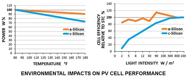
Environmental impacts such as temperature and light intensity effect PV cell performance differently based on the type of semi-conductor material, such as amorphous silicon and crystalline silicon shown above.
Image: Ronald Fergle3
Types of PV Modules
As PV cell technology continues to improve, component manufacturers continue to pioneer new ways of assembling cells into modules. Module manufacturers provide numerous variations based on cell types, cell wiring, module encasement materials, manufacturing techniques, installation applications, and customer performance expectations.
Commercially available, photovoltaic modules in mass production include:
- Monofacial
- Bifacial (Dual Glass, Transparent Backsheet)
- PERC (passivated emitter and rear cell)
- PERT (passivated emitter rear totally diffused)
- SHJ (silicon heterojunction)
- IBC (interdigitated back contact)
- CdTe
- CIGS
Crystalline Silicon
Crystalline silicon modules account for approximately 90% of the U.S. commercial market. Manufacturers offer modules with different c-Si cell technologies and features. Variations include: number of busbars (front electron contacts), tabbing (how cells are wired together), back-contact materials (backside hole transmission), and module encasement properties (transparent, opaque, colored). Bifacial (Dual Glass, Transparent Backsheet) modules can take advantage of direct and reflected solar radiation striking the module from the rear. Modules are typically guaranteed through warranties to produce at least 85% of their original power for a minimum of 25 years. Typical overall efficiency of commercially available crystalline solar panels range from 16% to 24%.
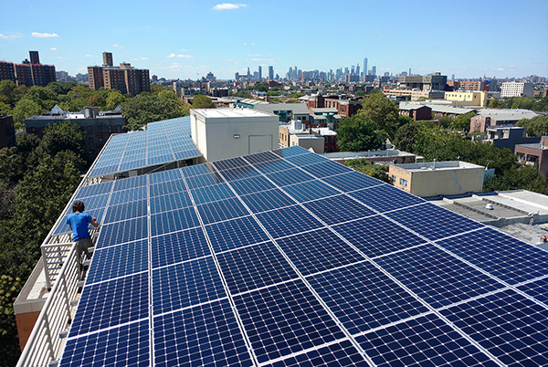
PV crystalline silicon (c-Si) roof-top installation in New York City.
Photo Credit: Bright Power, Inc., U.S. Department of Energy
Thin Film
Thin-film products are available in rigid and flexible versions. They are frequently used in building-integrated photovoltaic (BIPV) applications such as roof shingles, tiles, building facades, or the glazing for skylights. BIPV can be well blended into building architecture, providing an additional aesthetic option for designers.
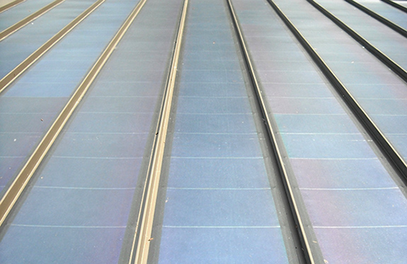
Thin-film collectors on a standing-seam metal roof.
Photo Credit: Architectsea, CC-BY-SA-3.0
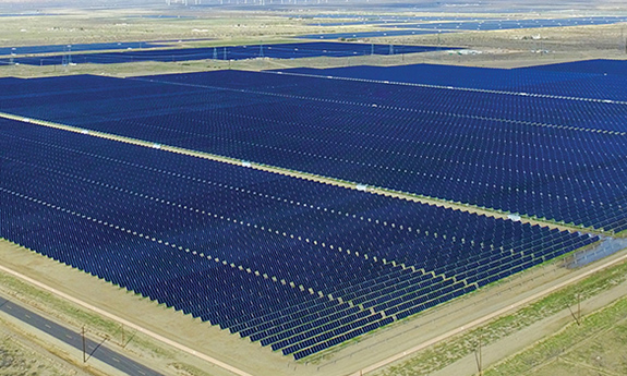
Thin-film utility-scale installation.
Photo Credit: First Solar
Costs Of PV Technology
Solar installations have many positive aspects regarding costs, whether they are categorized as financial, environmental, or social. The financial costs for module production as well as system installation continue to decline. The modeled market price (MMP) costs for residential applications average 2.95 $/watt, commercial projects 1.84 $/watt to 1.94 $/watt, and utility-scale installations 0.99 $/watt. MMP costs take into considerations market fluctuations and policy factors, and are useful for near-term policy and market analysis. NREL has compiled extensive information regarding installed system costs, including battery storage and O&M expenses, which are then analyzed based on market segment. Refer to the documents, "U.S. Solar Photovoltaic System and Energy Storage Cost Benchmarks, With Minimum Sustainable Price Analysis: Q1 2022" and "U.S. Solar Photovoltaic System and Energy Storage Cost Benchmarks, With Minimum Sustainable Price Analysis: Q1 2023" for more information.
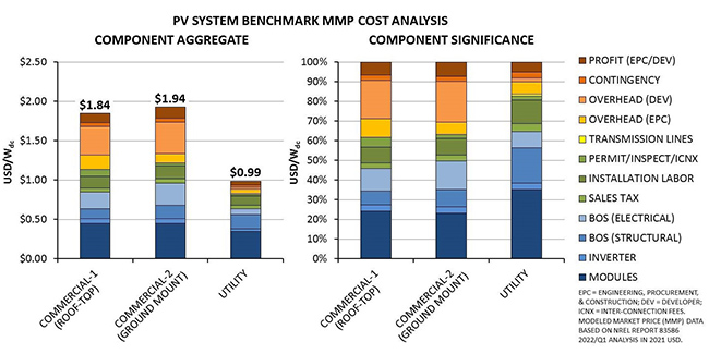
NREL analysis of PV system modeled market price (MMP) data show commercial-scale installations have dropped to between $1.84 and $1.94 per watt, and utility-scale installations to $0.99 per watt. The costs of modules, inverters, and BOS components for utility-scale projects are less per watt produced, but in turn have a greater influence on the over-all cost of an installation.
Image Credit: Ronald Fergle, (MMP data: NREL Report 835864)
The environmental costs of energy production are increasingly important as climate change impacts become more severe. PV systems generate "clean" electricity with no carbon footprint. Sunlight is a renewable, unlimited resource. While the manufacturing process of silicon cells is energy intensive, the carbon footprint should continue to drop as more modules are manufactured in the U.S. and additional grid-connected solar projects come online.5 In addition, the emerging PV cell technologies present even lower initial entrained energy levels. In terms of social costs, the U.S. solar industry now employs over 263,000 workers and continues to grow.6 Annually, solar installations coming on-line contribute the largest amount of new electricity generation capacity. In 2023, 53% of new capacity in the U.S. was due to PV installations (followed by natural gas at 18%, wind at 13%, and "other sources" the remainder).7
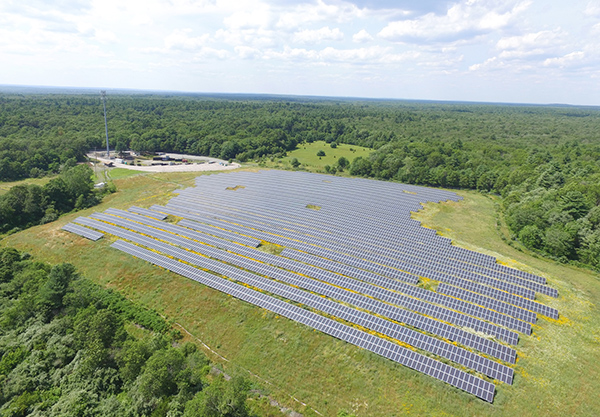
Utility-scale installation located over a retired landfill in Rehoboth, Massachusetts.
Photo Credit: Lucas Faria, U.S. Department of Energy
Application
When making a decision about photovoltaics and if they are a good match for a particular construction project, several factors should be considered. The most important is solar access. The site should not be shaded during the "solar window." This is defined as the period from three hours before solar noon (the highest point of the Sun in the sky) to three hours after solar noon. This is the time of the greatest amount of solar insolation. Solar gain before and after the solar window can still contribute significant amounts of energy to the overall daily collection, but the 9:00 a.m. to 3:00 p.m. period is the priority. Note that these times are based on the specific site longitude and solar noon, which is independent from generic time zones or daylight savings adjustments. Low slope roofs (typically called "flat roofs") and south facing roofs with minimal roof obstructions are also prime locations to pay attention to because of their potential increased amounts of solar insolation. For ground applications, it is best to use previously disturbed land to reduce National Environmental Policy Act (NEPA) compliance requirements.
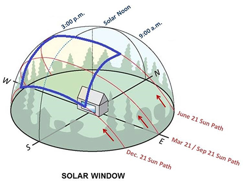
This image represents the "solar window" for a particular location. It is based on the path of the Sun in the sky at its highest location. A PV installation should be shade-free from three hours before solar noon to three hours after solar noon (as highlighted in blue).
Image Credit: NREL
There are three common types of photovoltaic system design:
- Grid-Tied without Battery Backup. The system is connected to the utility grid and has no batteries to store extra electricity
- Grid-Tied with Battery Backup. The system is connected to the utility grid and has battery storage to provide emergency power
- Stand-Alone with Battery Backup. The system is not connected to the utility and uses battery storage to provide the power needs of the location.
Grid-Tied photovoltaic systems without battery storage are the most common type of application. If the system is connected to the grid and has critical loads that need emergency backup power, a Grid-Tied with Battery Backup system is recommended. If the site does not have grid power and runs on generators, a Stand-Alone with Battery Backup system can reduce or eliminate generator run time, save fuel, and reduce operations and maintenance costs. PV installations with battery storage are expected to increase to 28% of all new distributed energy solar capacity in 2028; while utility-scale installations are expected to add another 3 GW annually of new storage capacity by that same time.8
The Federal Energy Management Program (FEMP)'s Integrating Renewable Energy into Federal Construction Guide has more information on assessing renewable energy options, and the following sections describe on-site and use characteristics, economics, potential power production, and operations and maintenance (O&M) requirements.
Economics
Photovoltaics will produce energy anywhere there is sunlight and will generate more where there is a lot of sun. However, economic viability depends not only on the solar resource, but on economic factors pertaining to the site. Economic incentives for photovoltaics, such as tax incentives or state renewable electricity requirements with specific solar targets, increase the value of solar-produced electricity. A common incentive is net-billing, which allows the user to offset the purchase of electricity from the utility with the production and contribution of electricity from the photovoltaic system.
Other key economic factors that can improve a photovoltaic system's viability are: high electricity rates, time of use electricity rates that are high during the sunny parts of the day, solar feed-in tariffs, and any other solar incentive.
Assessing Solar Resource Availability
The National Renewable Energy Laboratory (NREL) has developed detailed information on the solar radiation and other factors that contribute to the energy production from photovoltaic systems throughout the United States and in much of the world. The following map shows the United States' solar resource potential, with warmer colors indicating higher solar insolation levels.
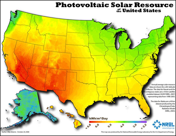
Photovoltaic solar resource in the United States
Credit: NREL
There are many software tools available to assist with the designing and modeling of PV system performance. An example is NREL's PVWatts™ solar calculator, which determines the energy production and cost savings of grid-tied PV systems throughout the world. It allows homeowners, installers, manufacturers, and researchers to easily develop estimates of the performance of hypothetical photovoltaic installations.
The solar design calculators work by creating hour-by-hour performance simulations that provide estimated monthly and annual energy production in kWh of electricity and equivalent dollar values. Users can select a location and choose to use default values or their own system parameters for size, electricity cost, array type and efficiency, tilt angle, and azimuth angle. The azimuth angle is the compass bearing toward which the modules are pointed. A system facing true north has an azimuth of 0°, due east 90°, south 180°, and west 270°.
Photovoltaic systems should ideally be designed and installed with an azimuth within 45° of true south (for the Northern Hemisphere) to maximize electricity production. Panels typically produce the most energy if tilted at an angle equal to the latitude of the location; but, specific site factors may dictate a different optimal orientation. In addition, avoid any shade on the photovoltaic modules.
Using typical meteorological year (TMY) weather data for the selected location, the PV calculators determine hourly performance data for the system and adjust for losses (both in production of energy and the conversion from DC to AC power). Hourly values are then combined to calculate monthly and annual energy production.
This information is particularly useful in matching photovoltaic output to seasonal electric loads. Running these calculators with different scenarios is also helpful in understanding the variations in system performance due to changes in over-all module size, angle, and orientation.
Design Considerations
When integrating photovoltaics into construction projects, it is important to consider the following design considerations:
- Provide south-facing roof area (45 to 80 ft2/ kW, depending on module efficiency)
- Provide blocking between rafters or other structural support as required
- Minimize roof penetrations. Provide support curbs, or roofing materials that accommodate connections on sloped roofs.
- Provide a pathway for electrical conduit to the electrical room
- Provide footprint or wall space in the electrical room for power conditioning equipment and accessories (consider outdoor locations for these)
- Determine the proper size of the main electrical service panel. Refer to NEC 690.64 for more information. "Line Side" connections are generally not allowed due to safety concerns, and "Load Side" connections are governed by the two conditions listed below. (Line Side connections are when PV array output is connected between the utility meter and the service panel main breaker; and Load Side connections are when the PV electricity is fed into the service panel after the main breaker.)
- First, the circuit breaker on the PV supplied power (also referred to as the Over Current Protection Device, or OCPD) can be no more than 20% of the main service panel rating (the "120% rule").
- Second, the OCPD must be sized for at least 125% of the PV inverter electrical output.
- For PV systems added to existing structures with smaller service panels, this may require an upgrade to the panel size. Another option is to de-rate the panel's main breaker (the breaker is changed to a smaller size), thereby providing additional capacity for the OCPD connection. Consult a licensed electrician for assistance.
- Integrate supplied energy performance data from the photovoltaic system into the overall building management control system (BMS).
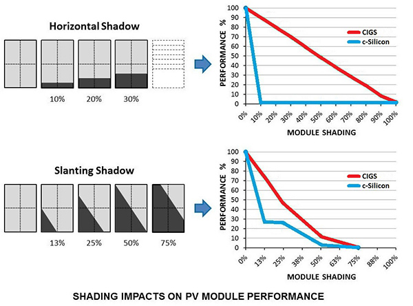
Shading impacts module performance differently based on the type of cell semi-conductor material and how the individual cells are wired together. Crystalline silicon modules typically have higher efficiency ratings, but are more susceptible to the negative effects of shading than are copper indium gallium (di)selenide (CIGS) modules. Selecting the appropriate type of module that best addresses the insolation conditions of the installation site is paramount.
Image: Ronald Fergle9
Procurement Considerations
Once a good solar project site has been identified, there are some general procurement points to consider regarding the financing/contracting mechanism selected for the project. General considerations include interaction with the utility to resolve interconnection issues, compliance with the NEPA requirements, review of the site master plan to confirm that the selected site will not interfere with planned future use, discussion of historic building issues, and ability to connect the system to building automation controls.
Photovoltaic projects often make use of renewable energy project funding to take advantage of tax incentives or other incentives. This can be complex for Federal agencies and will need to be carefully handled in procurement. Procuring Solar Energy: A Guide for Federal Facility Decision Makers provides more information and links to case studies.
Design and installation of a photovoltaic system should be conducted by organizations and individuals with experience in projects that are of a similar size and type to the one being proposed. Industry certification of solar providers is managed by the North America Board of Certified Energy Practitioners (NABCEP). Credential holders have undergone rigorous testing and are committed to professional and ethical practices.
For the construction phase of the project, rather than the typical design-bid-build format where a detailed design is created and then contractors bid on building the design, for photovoltaics it is recommended that a performance specification be used in a design-build scenario. Developers can then use their competitive advantages to create cost-effective designs that deliver the required performance.
The Federal Energy Management Program (FEMP)'s Integrating Renewable Energy into Federal Construction Guide has more information on renewable energy project funding.
Operations and Maintenance
Operations and maintenance (O&M) is important to ensure that a system operates optimally and safely, and will extend the life of the system components. Facility personnel should fully understand the system operation and safety procedures, whether the O&M is performed by them or a third-party contractor. The O&M could be part of a service contract that comes with the system installation package. O&M costs averaged $7.90/kW for utility-scale projects in 2022.10 For more information, visit PVResources.com.
FEMP's Integrating Renewable Energy into Federal Construction Guide has more information on O&M procedures.
Modules
Photovoltaic modules normally come with excellent manufacturer warranties for any manufactured defects. A regular visual inspection is a simple way to check for any damage that may have been caused by severe weather. Also, since dust build up on the module surface can decrease system performance, it is recommended that a module cleaning be performed one to two times per year, or as needed.
Inverter
Inverters are critical components of PV systems and they benefit from regular inspection to ensure peak performance. Excessive heat is detrimental to inverter longevity. Periodic maintenance to remove accumulated dust and maintain unobstructed air flow to the unit is recommended. Overloading and power surges can also damage the internal capacitors. String inverters have a typical design life of approximately 10 years and micro-inverters 20 to 25 years.
Battery Storage
Battery technologies and how they integrate into PV installations are continually improving. Since each type of battery storage system requires specific maintenance, it is recommended to refer to their product manuals for more in-depth guidance on maintenance and service.
Special Considerations
Special considerations for photovoltaics system design and installation include grid interconnection, environmental review and permitting, security issues, and relevant codes and standards.
Grid Interconnection
A photovoltaic system that will be connected to the utility grid must meet interconnection requirements of the local utility. Many states or localities have guidelines that limit the size of a project that can be interconnected, or place a grid-wide limit on the amount of capacity a utility must interconnect. Photovoltaic projects sometimes have different interconnection standards than other technologies, with the best resource being the local utility for the site. A federal agency should confirm early in the discussion with the utility if it can sign the utility interconnection agreement as there have been some cases where utility indemnification clauses prevented an agency from legally signing the agreement.
Rules also vary for net billing of interconnected systems, including availability of net metering, terms of the tariff, and the size of eligible systems. In many cases, the rules for photovoltaic systems vary from other energy sources. FEMP's Integrating Renewable Energy into Federal Construction Guide has more information on interconnection requirements and net metering.
Financing of photovoltaic systems often makes use of on-site power purchase agreements, where a third-party installs, maintains, and owns the photovoltaic system and then sells the power to the facility at a defined price for a specified period of time (anywhere from 10 to 25 years). Benefits to the facility owner include no up-front costs for installation of the PV system. The third-party retains any tax rebates or other financial incentives, but the PPA supplied electricity is typically purchased at a lower rate than utility-supplied electricity. Availability of solar PPAs vary by state, with more than half of all U.S. states currently allowing them.
The Database of State Incentives for Renewables & Efficiency (DSIRE) is a comprehensive source of information on state, local, utility, and federal incentives and policies that promote renewable energy and energy efficiency.
Environmental Review / Permitting
If the project is located on Federal land or uses Federal funding (besides a tax credit), the project must comply with NEPA. The effort involved to comply with NEPA greatly depends on where the project is located on the site and with the scale of the project. The impact of a rooftop system, for example, is typically less than that of a ground-mounted system which may be located in an environmentally sensitive area. Photovoltaic systems mounted on existing facilities typically qualify for a categorical exemption. Photovoltaics added to new construction should rarely add any additional burden to the NEPA process. Consulting with an agency or environmental expert on procedures for implementing NEPA is recommended.
Security
PV systems installed in highly visible locations may lead to vandalism or theft in certain situations. If this is a concern, particularly for a facility with little security or no security for extended periods of time, theft-prevention techniques should be set up accordingly.
Relevant Codes and Standards
There are various local and national codes and standards for distributed electric generator integration and interconnection with utilities. The following list identifies the existing codes and standards applicable to common photovoltaic installations.
Electrical Codes
Building Codes
- ICC, ASCE 7 (Minimum building design loads)
Standards
- IEEE 1547 Standard for Interconnecting Distributed Resources with Electric Power Systems
- UL 1703 Standard for Flat-Plate Photovoltaic Modules and Panels
- UL 1741 Standard for Inverters, Converters, Controllers and Interconnection System Equipment for Use With Distributed Energy Resources
In addition, an engineer's stamp is recommended to ensure adequate review of the structural weight carrying capacities of the roof, the wind loads have been taken into consideration, and to verify the overall code compliance of the final electrical design. The photovoltaic layout must also be checked to ensure compliance with fire specifications. See the GSA Fire Safety Guideline for Photovoltaic System Installation for more information.
Additional Resources
Websites
- DOE's EERE Solar Photovoltaics Technology Basics gives a brief description of how the photovoltaic materials convert sunlight into electrical energy.
- Database of State Incentives for Renewables & Efficiency (DSIRE) provides a comprehensive list of federal, state, and local incentives that promote renewable energy and energy efficiency.
- North American Board of Certified Energy Practitioners (NABCEP) provides an industry certification of experienced photovoltaic installers. NABCEP was designed to raise industry standards and promote consumer confidence in photovoltaic and solar thermal system installations.
- National Center for Photovoltaics (NCPV) focuses on innovations in photovoltaic technology that drive industry growth in photovoltaic manufacturing nationwide. Formed by the U.S. Department of Energy (DOE) and based at NREL, the NCPV focuses on research and development and increasing U.S. competitiveness.
- NREL's PVWatts calculator determines the energy production and cost savings of grid-connected photovoltaic energy systems throughout the world.
- Procuring Solar Energy: A Guide for Federal Facility Decision Makers provides an overview of federal facility managers and their procurement terms on the process of installing solar electric and solar thermal systems.
- Sandia National Laboratories teams with the U.S. Department of Energy, industry, and academia to improve the performance and reliability of photovoltaic technologies and grid integration.
Organizations
- American Solar Energy Society (ASES) is the nation's leading association of solar professionals and advocates. It provides listings of solar businesses within each state.
- Smart Electric Power Alliance (SEPA) provides information about solar technologies, policies, and programs.
- Solar Energy Industries Association (SEIA) is the national trade association of the solar energy industry. It provides numerous analyses of solar data, including statistical information regarding installed capacity, module costs, and installation costs.
Publications
- Best Practices for Siting Solar Photovoltaics on Municipal Solid Waste Landfills , May 2022, Environmental Protection Agency (EPA)
- Publications, National Renewable Energy Laboratory (NREL)
- Research and Analysis, Rocky Mountain Institute (RMI)
- Resources, Office of Energy Efficiency and Renewable Energy (EERE)
- Solar Industry Research Data, SEIA
- State, Local, & Tribal Governments Community Solar, NREL
- Technology Roadmap, Solar Photovoltaic Energy, 2014 Edition, International Energy Agency
- U.S. Solar Market Insight, SEIA
- U.S. Solar Photovoltaic System and Energy Storage Cost Benchmarks, With Minimum Sustainable Price Analysis: Q1 2022 , NREL
- U.S. Solar Photovoltaic System and Energy Storage Cost Benchmarks, With Minimum Sustainable Price Analysis: Q1 2023 , NREL
Training Courses
Endnotes
1. [See NFPA 70 National Electrical Code (NEC) 690.12, or ICC 690.12]
2. [Efaz, Erteza Tawsif; Rhaman, Md Meganur; Imam, Safayat Al; Bashar, Khandaker Lubaba; Kabir, Fahmid; Mourtaza, MD Ehasan; Sakib, Syed Nazmus; Mozahid, F. A. (September 1, 2021). "A review of primary technologies of thin-film solar cells"; and Engineering Research Express. 3 (3): 032001. Bibcode:2021ERExp...3c2001E; and doi:10.1088/2631-]
3. [Data per Polysolar Ltd. research; also see: Ebhota, W.S.; Tabakov, P.Y. (September 2022), "Influence of photovoltaic cell technologies and elevated temperature on photovoltaic system performance" Ain Shams Engineering Journal 14 (2023) 101984, www.sciencedirect.com]
4. [Ramasamy, Vignesh; Zuboy, Jarett; O'Shaughnessy, Eric; Feldman, David; Desal, Jal; Woodhouse, Michael; Basore, Paul; Margolis, Robert (September 2022), "U.S. Solar Photovoltaic System and Energy Storage Cost Benchmarks, With Minimum Sustainable Price Analysis: Q1 2022" Technical Report NREL/TP-7A40-83586]
5. [Liang, H., You, F. Reshoring silicon photovoltaics manufacturing contributes to decarbonization and climate change mitigation. Nat Commun 14, 1274 (2023). https://doi.org/10.1038/s41467-023-36827-z]
6. [Interstate Renewable Energy Council (IREC) "13th Annual National Solar Jobs Census 2022", Executive Summary, July 2023]
7. [Wood Mackenzie/SEIA US Solar Market Insight®, "US Solar Market Insight Executive Summary 2023 Year in review", March 2024]
8. [SEIA Solar Industry Research Data, "Storage is Increasingly Paired with All Forms of Solar" https://www.seia.org/research-resources/solar-market-insight-report-2020...
9. [Data per Hulk Energy Technology research; also see: Lin, Guoqian; Bimenyimana, Samuel; Tseng, Ming-Lang; Wang, Ching-Hsin; Liu, Yuwei; Li, Lingling (December 2020), "Photovoltaic Modules Selection from Shading Effects on Different Materials" Symmetry 2020, 12(12), 2082; https://doi.org/10.3390/sym12122082]
10. [PV Magazine, October 4, 2023, Pilar Sanchez Molina, "US solar O&M contract prices averaged $7.90/kW in 2022, says WoodMac"]