Introduction
Within This Page
To select, detail, and specify the most appropriate roof system for a project; past experience with several of the available material options and an understanding of roof assembly materials and system options, and an understanding of roof design considerations is recommended. The purpose of this section is to provide design guidance for designing high-performance low- and steep-slope roof assemblies. This document relies on many other industry standards, which should also be consulted. It is the intent to provide recommendations beyond the content of those standards, especially as they relate to integrating the roofing assembly into a total building enclosure and mechanical system design. It is intended to provide a "Best Practice" and shall not be construed in any manner to establish the legal standard of care required from licensed professionals.
Prior to the mid-to-late 1970s, almost all low-slope roofs were asphalt or coal tar built-up roofs. In fact, in the earlier part of the century, coal tar roofs were often used to cool buildings by allowing the intentional ponding of water on the coal tar surface of the roof for evaporation and cooling effect. Coal tar pitch is not composed of solvents like asphalt, and so will not dissolve and evaporate the solvent oils out of the roofing compound like asphalt in a pond situation. This is why coal tar pitch can be applied on a dead level roof surface; ponding water has no negative effect on it. Type I Coal Tar Pitch has good adhesive and self-healing properties and is used with aggregate surfacing on roof slopes up to 1/8":12. Designers should specify coal tar for use in coal tar built-up roof membranes comply with ASTM Standard D450, Type I. Also, coal tar built-up membrane systems should be detailed in accordance with manufacturer requirements; especially at drains, scuppers, and roof edges.
Asphalt continues to be the more common built-up roofing material compared to coal tar pitch. One must be aware of the critical difference in the oil solvent composition of asphalt, in that these solvents can leach out of the asphalt in ponding conditions, evaporate off, and leave the asphalt membrane dried and cracked just where the ponding is most prevalent. Be aware that, for this reason, asphalt roofing manufacturers require a minimum of 1/4" slope per foot to prevent any possibility of ponding. Manufacturers typically consider moisture that remains on the roof surface OK as long as it evaporates within 48 hours under conditions conducive to drying. Asphalt system warranties are typically void for slopes less than 1/4" per foot, and certainly where any ponding occurs, which unfortunately, is where leaks will occur.
During the last two decades of the 20th century, a variety of other types of low-slope roof systems began to compete with traditional built-up roofs (BUR). These newer systems included modified bitumens, single-plies, sprayed polyurethane foam, metal panels, and reinforced liquid-applied roof membranes. Liquid-applied roofing was added to the International Building Code, 2012 Edition (IBC 2012) in Section 1507.15. The NRCA has a section and details for this type of roofing in The NRCA Roofing Manual: Membrane Roof Systems.
While the modified bitumen systems are related to BUR, the other low-slope alternatives are radically different. Along with new choices of membrane materials, plastic foam roof insulations also emerged in the 1970s. The abundance of materials and applications from which to choose has created a complex and challenging subject matter.
Note: Low-sloped roofs are defined as those roofs with a slope less than or equal to 3:12 (25 percent). However, with the exception of metal roofs, most low-slope roofs have a slope of about 1/4:12 (2 percent) slope. It is recommended that low-slope roofs have a slope of 1/2:12 (4 percent) where possible. Steep-slope roofs are defined as those roofs with a slope greater than 3:12 (25 percent). As discussed in the Description section, some materials can be used on both low- and steep-slopes, while others are limited to either low- or steep-slope. Steep slope materials may require additional enhancements when installed on slopes less than 4:12 (33 percent).
Scope
The Description section discusses roof assembly materials, including roof decks, air and vapor retarders, roof insulations, and roof coverings. The Application section discusses system selection criteria, warranty considerations, key elements of drawings and specifications, and construction contract administration. The Details section discusses and presents various details. The remaining sections are Emerging Issues, Relevant Codes and Standards, and Additional Resources.
This Guide is intended to give a relatively brief introduction to roofing, to weigh pros and cons of various materials that are not available in other reference documents, and to provide some suggestions for enhancements beyond systems that simply comply with code and warranty minimums. It addresses the basics, but does not delve deeply into the subject. After gaining a general understanding of the roof assembly options and various issues associated with them, the designer has a choice to make: Either elect to further expand your skills and knowledge, or work with professional roofing contractors or roof consultants. Years ago, it was uncommon for designers to work with a roof consultant or call upon a trusted contractor for advice. But the complexities brought on by the BUR alternatives now demand the inclusion of a roof consultant as part of the design team, if this expertise is not developed within the designer's office.
For below-grade waterproofing and plaza decks, see Below Grade Systems. For seismic considerations, see Seismic Safety. For blast considerations, see Blast Safety.
Project Delivery
Delivering a successful roof project involves two distinct phases. The first phase is the design process. It is imperative to identify all of the criteria and required performance characteristics early in the design process. A roof system should be selected that optimally responds to an integration of the project's requirements and the system selection criteria. After the roof system is selected, the specifics of the system (such as deck type, insulation type(s) and thickness, fastener patterns, and warranty requirements) are developed and details are designed. This phase is culminated with the preparation of specifications and drawings that communicate the designer's design concept and requirements to a professional roofing contractor for execution of the work.
The second phase is construction contract administration. In addition to the traditional activities, such as submittal review and field observation, the roof designer should also inform the building owner about the importance of semi-annual roof inspections and routine maintenance.
Material Descriptions
When specifying roof assemblies, designers have many materials from which to choose. This section provides a brief overview of the primary roof deck, air barrier, vapor retarder, insulation, and roof covering materials used in the U.S. For further information on these materials, refer to The NRCA Roofing Manual (published by the National Roofing Contractors Association). Roof system selection criteria are discussed in the Application section. Combining the various materials into assemblies is also discussed in The NRCA Roofing Manual and for roofing systems on Federal buildings see United Facilities Criteria UFC 3-110-03.
A design concern when designing roofs in cold climates is the possibility of falling ice and snow, as described in Considerations for Building Design in Cold Climates by Mike Carter, CET and Roman Stangl, CET.
The term roof system refers to the air barrier or vapor retarder (if present), roof insulation (if present), and the roof membrane, flashing, and accessories.
Low-slope Roof Coverings (slope less than or equal to 3:12):
- Built-up Roofs (BUR)
- Mesh Reinforced Elastomeric Coatings (MREC)
- Modified Bitumen (MB)
- Atactic Polypropylene (APP)
- Styrene-Butadiene-Styrene (SBS)
- Styrene-Ethylene-Styrene (SEBS)
- Single-ply
- Thermoplastic Single-Plies
- Polyvinyl Chloride (PVC)
- Thermoplastic Polyolefin (TPO)
- Ketone Ethylene Ester (KEE)
- Thermoset Single-Plies
- Ethylene Polypropylene Diene Monomer (EPDM)
- Thermoplastic Single-Plies
- Sprayed Polyurethane Foam (SPF)
- Metal Panels
- Hot and Cold fluid-applied roofing membranes
Steep-slope Roof Coverings (slope greater than 3:12):
- Metal Panels and Shingles
- Asphalt, Wood, and Synthetic Shingles
- Wood Shakes
- Clay and Concrete Tile
Roof Decks
Commercial and institutional buildings typically have steel or concrete roof decks, although plywood or OSB decks are also used on smaller buildings. The deck can have significant influence on the roof system.
Of the deck types used today, steel is the most common. Although prime-painted steel decks with welded connections are commonly specified, it is recommended that galvanized decks be specified in order to obtain greater corrosion protection in the event of roof leakage. It is also recommended that screw, pneumatic, or powder actuated-attachment be specified in lieu of welding, because screws provide more reliable attachment. Refer to the NRCA's Industry Issue Update, "Moisture in Lightweight Structural Concrete Roof Decks."
Also, the NRCA recommends steel roof deck installations conform to the requirements described in the Steel Deck Institute's (SDI's) Manual of Construction with Steel Deck and Composite Steel Deck Handbook. Review attachment with structural engineer who makes the final decision and specifies. In cold climates, it is a common occurrence for interior vapor to pass through simple laps in steel decking, and then condense in the roofing insulation to saturate the insulation and leak back through the deck joints as free water. In the case of cold climates, it is always best to provide a continuously sealed vapor barrier under the roof insulation, on top of the steel decking. If roofing materials are to be adhered to a new concrete deck verify that the concrete is cured, sufficiently dry, and that moisture test results are within the manufacture's recommendations for good adhesion.
Make sure the structural engineer designed the deck for the wind uplift loads, especially at the perimeter and corner zones.
Air Barriers
If the roof membrane is monolithic (i.e., a membrane roof) it serves as an air retarder. However, separate air barriers are sometimes incorporated into roof systems. When air barriers are incorporated into wall systems, they are normally included to control air movement, control moisture and/or reduce energy consumption, or to prevent pumping due to wind, which can cause uplift with mechanically fastened membranes. When an air barrier other than the roof membrane is incorporated into a roof system, it is normally included to address wind performance issues as discussed in Wind Safety, or to address a building code requirement. To reduce the potential of interior air being pumped into the roofing system an air barrier should be located at the roof deck level under the roof insulation, sealing all roof deck voids.
The deck itself can be a barrier if it is monolithic, such as cast-in-place concrete. When the deck is used as an air barrier, deck penetrations such as plumbing vents should be sealed, and the deck should be sealed at parapets. However, a separate sheet material such as 6-mil polyethylene, approved housewrap, a two-ply built-up membrane or a one-ply modified bitumen sheet is typically used to create an air barrier. Membranes used as air barriers, must be made airtight at all penetrations. Air barriers are further discussed in A Guide for the Wind Design of Mechanically Attached Flexible Membrane Roofs, which is available from the National Research Council Canada.
Requirements for air barriers are included in some building codes and widely adopted standards such as International Energy Conservation Code (IECC), 2012 edition and American Society of Heating, Refrigerating and Air-Conditioning Engineers (ASHRAE) Standard 90.1–2010 and –2013—Energy Standard for Buildings Except Low-Rise Residential Buildings.
Also refer to The NRCA Roofing Manual: Architectural Metal Flashing, Condensation and Air Leakage Control, and Reroofing for air barrier and vapor retarder requirements.
Vapor Retarders
Vapor retarders are materials with a perm rating of 0.1 or less and are typically sheet materials such as 6-mil polyethylene, a two-ply built-up membrane or a one-ply modified bitumen sheet. Housewrap should not be used for a vapor retarder because it has inadequate vapor flow resistance.
The presence of a vapor retarder can make it difficult to find leaks, as they can carry water great distances from the source of the leak. However, as discussed above under Roof Decks, vapor retarders must be used on all new concrete decks and on steel decks wherever there is a high humidity occupancy below, especially in cold climates. To be effective, vapor retarders must be airtight at all penetrations. Vapor retarders may also be required to prevent condensation under white or light-colored membranes (cool roofs) in cold climates because the temperatures of such membranes may be so low that even occupancies with low or average interior humidity can cause condensation in such circumstances.
As noted above, if the deck is a new concrete deck, a vapor retarder must be provided on top of the deck, to keep moisture inherent in new concrete decks from migrating into the roof system. This is true, regardless of the building occupancy's interior relative humidity.
Insulation
There are three categories of roof insulation: rigid board, non-rigid (batt, blanket, or loose fiber) and sprayed polyurethane foam. Rigid boards are typically used in low-slope assemblies. They may be polyisocyanurate (most common), extruded polystyrene, or mineral wool. Non-rigid insulations are typically used in attic spaces and in pre-engineered buildings. See the section on Sprayed Polyurethane Foam for more information on this type.
Cover Boards
A cover board is a thin layer of insulation (such as perlite or wood fiberboard or dense polyisocyanurate) or glass mat gypsum roof board, preferably pre-primed. Plywood and oriented strand board are occasionally used if required for high-wind speed uplift warranties. Cover boards should be placed over the primary thermal insulation (typically one of the plastic foam insulations) in order to provide enhanced physical characteristics, such as improved fire and compressive resistance, prevention of delamination of facers due to traffic on the roof, provision of improved wind uplift resistance, and to avoid blistering or avoid a compatibility problem.
Cover boards are also commonly used in re-covering to improve the application surface; to cover joints between insulation boards; and to provide a separation layer between the existing and new roof membranes. When used in this application they are often referred-to as "recovery board."
Cover boards in commercial construction are typically glass mat gypsum roof board (preferably pre-primed) or perlite. Some materials used for cover boards are sometimes specified for use as an underlayment board directly over steel roof decks in order to provide a thermal barrier to provide fire protection between steel decks and certain types of plastic foam insulation (the IBC specifies thermal barrier requirements) or to provide a smooth surface for a vapor retarder. Note that perlite will absorb water more readily than glass mat gypsum board; this may be a consideration if there is a leak.
Rigid Insulation Boards
Rigid, or Board-stock insulation, typically has sufficient compressive strength to support the roof membrane and the loads placed upon it. In addition to supporting the roof membrane, rigid insulation can provide other functions for the roof system such as a uniform surface for membrane application and improved hail resistance. Rigid insulation is commonly used to achieve slope in low-slope applications where the deck does not provide the necessary slope. Tapered insulation typically provides 1/4" to 1/2" of slope. Insulation should typically be applied in two layers with offset joints to minimize thermal bridging.
The following common types of rigid insulation boards are available:
Perlite: This is an open-cell low R-value insulation (R-2.78 per inch) that is commonly used as a cover board (see Note below). It has good fire resistance, but when exposed to water, it loses compressive resistance, turns to mush, and can be easily compressed. Half-inch thick boards have a greater percentage of organic material content than do 3/4" or thicker boards. Hence, when hot asphalt is applied over 1/2" boards, the potential for the development of blisters in built-up and hot-applied modified bitumen membranes is increased. For these reasons, perlite is generally not recommended.
Polyisocyanurate: There have historically been issues with aging of polyisocyanurate affecting R-value. Nevertheless, polyisocyanurate is a high R-value insulation (R-5.6 per inch thickness in cooling conditions and R-5.0 per inch thickness in heating conditions using NRCA's "in-service" recommendation, or approximately R-5.7 for one inch thickness using the Long-Term Thermal Resistance (LTTR) method for determining resistance).
Polyisocyanurate is one of the plastic foam insulations. It is widely used in low-slope roof systems. Polyisocyanurate insulation is inherently more fire-resistant than polystyrene insulation. It always comes with facers, which are thin sheets on both faces of the insulation, because facers are necessary in the production process. Note that the foam insulation can compress and facers can delaminate when subjected to heavy traffic, therefore a cover board is always recommended. Also, facers act as vapor retarders, which may or my not be desirable.
Consider using the 25 psi product instead of the standard 20 psi. If subjected to a leak condition, polyisocyanurate will absorb moisture, lose its insulating value, and will have to be replaced in correction, unlike polystyrene, which can often be reused. Although more fire-resistant than polystyrene, it should be verified with the manufacturer if a thermal barrier (see next paragraph) is required. Polyisocyanurate is less expensive than extruded polystyrene.
Polystyrene: There are two types of polystyrene insulation: expanded polystyrene (sometimes referred to as EPS or bead-board) and extruded polystyrene (sometimes referred to as XPS). The two types have distinctly different properties. Polystyrene is one of the plastic foam insulations and should be used with caution where hot roofing materials are employed. The International Building Code requires a fire separation layer called a "thermal barrier" with polystyrene insulation used over a steel deck. This is usually a 1/2 inch sheet of gypsum directly above the deck.
Polystyrene boards should not be in direct contact with PVC membranes, otherwise the polystyrene will leach plasticizers out of the PVC. A suitable separator needs to occur between polystyrene and PVC.
Expanded Polystyrene (EPS): EPS is sometimes referred to as "molded expanded polystyrene" or "bead-board." This is moderate R-value insulation (from slightly less to slightly more than R-4 per inch, depending upon density). The low-density product is relatively inexpensive. Solvent-based adhesive and hot asphalt disintegrate EPS. Hence, if either of these is used, a suitable cover board needs to be installed over the EPS. EPS can also be decomposed or melt at high temperatures. Therefore, EPS should not be used underneath a black membrane unless a suitable cover board is installed between the EPS and the membrane. The National Roofing Contractors Association (NRCA) recommends expanded polystyrene insulation intended for use as rigid board roof insulation have a minimum density of a nominal 1.25 pounds per cubic foot, that complying with ASTM C578, type VIII, having a minimum density of 1.15 pounds per cubic foot. EPS cells are filled with air. Therefore, unlike the other plastic foam insulations, EPS does not thermally age (i.e., loose R-value over time). EPS is not very resistant to water vapor; when exposed to water vapor drive, EPS can absorb a considerable amount of moisture.
Extruded Polystyrene (XPS, sometimes EXPS or XEPS): This is a high R-value insulation (R-5 per inch for products with a minimum compressive resistance of 25 psi, R-4.6 per inch for products with a minimum compressive resistance of 15 psi). Generally products with an R-value of 5.0 per inch thickness are used in roof applications. Some manufacturers offer XPS made from recycled XPS.
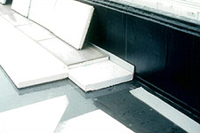
Figure 1. This PMR has of two layers of XPS. The top board has a factory-applied mortar surface.
A cover board is usually required with XPS, to provide a surface to adhere the membrane (XPS is not available with facers). XPS is very resistant to water vapor drive. However, as with EPS, XPS should not be exposed to solvent, hot asphalt, or very high temperature. But unlike EPS, in order to avoid membrane splitting, XPS should not be used below a built-up or modified bitumen membrane (even if a cover board is installed over the XPS).
XPS is the only insulation suitable for use above the roof membrane in protected membrane roof (PMR) systems (see section on this topic). However, boards intended for PMRs need to be specifically manufactured for this application. Some minor water absorption may occur in boards located above the membrane during the roof's service life. To account for the R-value reduction due to the water absorption, it is recommended that the roof designer reduce the board's initial R-value by 10%.
XPS can often be re-used when re-roofing, because it does not absorb water when there are the inevitable leaks, distinguishing it from the more commonly used polyisocyanurate insulation. That, combined with the required use of a cover board with XPS, which increases durability, is why the life-cycle cost of XPS insulation is often better than polyisocyanurate insulation.
XPS boards with extremely high compressive resistance are available for use in plaza decks where high compressive loads occur. 40 psi is recommended for light pedestrian loads, 60 psi is recommended for heavy pedestrian loads with light vehicular traffic, 100 psi is recommended for heavy vehicular traffic.
Mineral wool: R-4 (approximate) is not seen very often in low slope roofs, except as a replacement for fiberglass insulation between roof rafters in residential construction. Cover board or a rigid upper layer is required that is integral with the mineral wool (or sheathing in residential construction).
Composite boards: Composite boards typically consist of two layers of different types of insulation that are laminated together in a factory. The primary insulation is typically polyisocyanurate or EPS. The secondary layer is typically perlite, wood fiberboard, oriented strand board (OSB), plywood, or gypsum board. Composite boards made with OSB or plywood are commonly referred to as "nail base." Some nail base products have a small ventilation cavity between the primary insulation and the OSB or plywood. OSB and fiberboard composites are not recommended, as they do not withstand incidental wetting.
A nail-base insulation product should be checked to make sure it possesses adequate compressive strength and shear strength to withstand the loads expected for the roof system. For vented nail-base insulation, the product should be checked to make sure the spacer material and distance between spacer blocks provides adequate compressive strength, and the bearing surface of spacers provides adequate shear strength.
With some composite boards, the secondary layer (which is typically the top surface) is superficially adhered to the primary layer. With these boards, it is important to mechanically attach the composite board rather than adhere it. Otherwise the secondary layer could easily detach. The designer should understand that joints between the boards and the fasteners will represent a path for thermal bridging, therefore composite insulation is recommended to be installed over an underlying layer of non-composite insulation. The top layer composite insulation may be used in lieu of a separate insulation cover board.
For all types of insulation, is recommended to use multiple layers, with staggered joints. Joints over 1/8" wide are usually filled with spray foam insulation, especially if there is only one layer of insulation. Consider using maximum 4 by 4 foot boards to reduce the gaps caused by shrinkage of the insulation.
Batt, Blanket, and Blown-in Insulation
This type of insulation is commonly used to insulate attic spaces. The building code typically requires that the space between batt insulation and a low-slope roof be ventilated to the exterior which creates a myriad of issues related to control of air infiltration out of the ceiling of the spaces below. It is better to avoid the situation all together and use rigid insulation on top of the deck with a water-resistant air and vapor retarder membrane below and cover board or sheathing above. Blanket insulation is commonly used to insulate roofs of pre-engineered metal buildings. Fiberglass insulation is the most common batt/blanket insulation, and it is also available as a blown-in product. Mineral wool is also available in configurations suitable for roofing; it has a higher compressive strength than fiberglass. Cellulose (recycled newsprint) is also a common blown-in insulation. If cellulose is specified, specify a product that has been treated for mold and fire resistance.
Note: Batt insulation is insulation that is factory pre-cut into lengths of approximately 4', 8' or 9' and bundled without rolling. Blanket insulation is insulation that is supplied in a roll.
Sprayed Polyurethane Foam Insulation
Sprayed polyurethane foam (SPF) insulation systems are self-adhering, two-component materials, that are applied directly to roof decks, and may be used as an insulation and air barrier when applied to the underside of a roof deck, or it may be used in combination with one of several types of protective coatings as the primary roof covering. SPF insulation is available as closed cell or open cell in varying levels of vapor permeability so coordination with the primary roof covering is required to prevent moisture problems. Refer to the SPF roofing section below for additional information on its use as a primary roof covering.
Low-Slope Roof Coverings
The following membranes are typically used on low-slope roofs, but may also be used on steep-slope roofs. When used on steep-slopes, the system's fire resistance may be reduced and/or special precautions may be needed when used on steep-slopes.
Plaza Decks and Vegetated Roofs
Low slope roofing is sometimes accomplished by using a Plaza Deck or an Extensive Vegetative Roofs.
Built-up Roofs (BUR)
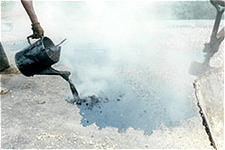
Figure 2. Bitumen is poured and aggregate surfacing is shoveled onto a built-up roof.
Built-up roof membranes are composed of alternating layers of bitumen (either asphalt or rarely coal tar) and reinforcement sheets (felts). Fiberglass felts are typically used for asphalt BURs Historically, ply sheets have been either fiberglass-mat or organic-mat reinforced. Currently organic-mat reinforced ply sheets have largely disappeared from the U.S. market. The asphalt is typically hot applied, however, cold-applied asphalt is available (cold-applied asphalt incorporates solvent). The membrane is either adhered to the substrate in bitumen or a base sheet (i.e., a heavy felt) is mechanically attached.
When a BUR is installed over polyisocyanurate, a suitable cover board should be installed over the polyisocyanurate. Four plies of felt are recommended (if a nailed base sheet is installed, four plies are recommended in addition to the base sheet). "Heavy duty" fiberglass felts are available (ASTM E2178 Type VI), but because of their stiffness, it is easier to construct unwanted voids in the membrane. Therefore, Type IV felts are recommended. Polyisocyanurate is by far the most common insulation used under built-up roof assemblies. Occasionally, mineral wool will be used.
The bitumen provides the waterproofing characteristics; the felts provide improvements to physical characteristics. Complete and full embedment of the felts into the bitumen is crucial.
Exposed asphalt is susceptible to ultra-violet degradation. Therefore, BURs are surfaced with aggregate, a field-applied coating or a mineral surface cap sheet. If aggregate is specified, wind blow-off should be considered, see Wind Safety—Roof Systems. Coatings include aluminum-pigmented asphalt, asphalt emulsion (reflective or non-reflective), urethane, and acrylic. Coatings can enhance fire resistance. However, if coatings are specified, periodic recoating will be required. Because of future maintenance demands, coatings are not recommended. If a cap sheet is specified, it should be in addition to the 4 plies of felt.
Asphalt tends to get brittle with age, making it unable to accommodate normal building movements. And, application of hot asphalt requires open flames and working with extremely hot liquids. Some clients and designers do not use BUR roofs to avoid these safety issues. Fumes are particularly noxious to many people and should be avoided on occupied buildings.
ASTM standard D312 is the product standard for asphalt used in roofing. There are four types of asphalt. Type I is much more susceptible to flow than Type IV. ASTM D6510 provides guidance for selection of asphalt Type in BURs. Caution should be used when heating asphalt to prevent changing its physical properties and thereby making it unsuitable for roofing.
Base flashings of BURs are typically constructed with modified bitumen sheets.
Pros and Cons for BUR
| PROS | CONS |
|---|---|
| Long and proven history when properly installed. | Particularly sensitive to experience and knowledge of the installer |
| Easily repaired | Asphaltic materials do not naturally possess optimal long-term performance characteristics. |
| Robust | Safety issues related to installation |
| Noxious fumes |
Although coal tar is the only roof covering noted in the International Building Code as being suitable for slopes as low as one-eighth unit vertical in 12 units horizontal for new construction and is still available, the vast majority of BURs are constructed with asphalt. Coal tar pitch is suspected to be carcinogenic and most owners and designers avoid it for that reason, in spite of the excellent performance characteristics.
Modified Bitumen (MB)
The physical characteristics of asphalt are actually not well suited to roofing; they are not UV stable, get brittle with age and cold, crack, alligator, and otherwise degrade relatively quickly. In order to make the asphalt more suitable for roofing, it is modified with other chemicals. MB membranes exhibit general toughness and resistance to abuse. They are typically composed of pre-fabricated polymer-modified asphalt sheets with a reinforcement layer. Polymers are added to bitumen to enhance various properties of the bitumen. The quality of MB products is highly dependent on the quality and compatibility of the bitumen and polymers, and the recipe used during the blending process. They are also highly dependent on the reinforcement within the sheet. High quality manufacturers carefully monitor the source of their raw asphalt and how it is modified. There are unfortunately many MB manufacturers and not all are as diligent.
There are three primary types of MB sheets, as well as field-applied modified mopping asphalt:
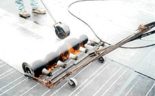
Figure 3. This APP modified bitumen cap sheet is being applied with a multi-head torch. The seam is being rolled with a roller.
Atactic polypropylene (APP): APP polymer is blended with asphalt and fillers. The mixture is then factory-fabricated into rolls that are typically one meter wide. The prefabricated sheet is typically reinforced with fiberglass, polyester, or a combination of both. The sheets are available in base, interply, and cap sheet variety. Sheets are smooth (i.e., un-surfaced); embedded with mineral granules of a variety of colors; or factory-surfaced with metal foil such as aluminum, copper, or stainless steel. The aluminum foil is available in colored finishes. APP MB membranes are generally resistant to high-temperature flow.
To avoid surface cracking from ultra-violet radiation, a field-applied coating (such as aluminum-pigmented asphalt, asphalt emulsion, or acrylic) may be applied. Cap sheets with factory-applied surfacing of granules or metal foil should be specified.
APP MB roofing systems are typically composed of a base sheet, an interply sheet, and a cap sheet. The cap sheet is either heat-welded (i.e., torched) to the base sheet, or it is adhered in cold adhesive. Mechanically attached systems are also available.
Note: APP MB sheets are also available with a factory-applied adhesive on the underside of the sheet, which permit them to be self-adhering. Several manufacturers introduced these products in the early 2000s.
Sometimes one or more fiberglass ply sheets (as used in BUR) are mopped to the base sheet or additional layers of APP sheet (sometimes referred to as "interply sheets") and then the cap sheet is installed. The interply sheet(s) provide redundancy. Note that these systems diminish some of the benefits of MB by introducing unmodified asphalt.
APP MB membranes can also be used in a protected membrane roof (PMR) configuration, also called inverted roof membrane assembly (IRMA). In a PMR, XPS insulation is placed over the membrane. The insulation is protected from ultraviolet (UV) radiation and wind blow-off by concrete pavers or large aggregate. When aggregate is selected, a filter fabric should be specified between the aggregate and insulation in order to keep the aggregate from getting into the board joints and underneath the boards.
Styrene-Butadiene-Styrene (SBS): SBS polymer is blended with asphalt and fillers. The mixture is then factory-fabricated into rolls with reinforcement and surfacing similar to APP MB sheets. SBS sheets generally have good low-temperature flexibility and weatherability compared to APP.
SBS MB is susceptible to premature deterioration when exposed to UV radiation and is typically specified with a factory-fabricated mineral surfaced modified bitumen cap sheet.
SBS MB membranes are typically specified as two or three ply systems. Specify 3 ply consisting of nailed modified bitumen base sheet, modified bitumen interply sheet, and modified bitumen cap sheet over nailable deck. The base sheet should be adhered when decking is non-nailable.
Note: SBS MB sheets are also available with a factory-applied adhesive on the underside of the sheet, which permit them to be self-adhering after removal of a carrier sheet. Several manufacturers introduced these products in the early 2000s.
SBS MB roofing systems can also be used in a Protected Membrane Roof (PMR) (sometimes referred to as an Inverted Roof Membrane Assembly (IRMA)) configuration. If a PMR system is specified, a slip-sheet recommended by the membrane manufacturer should be placed between the membrane and the XPS to prevent the insulation boards from bonding to the membrane. Otherwise, membrane tearing could occur when the insulation moves or floats during a rainstorm.
Styrene-Isoprene-Styrene (SIS): These seldom-used self-adhering sheets are blended with SIS polymer, asphalt and fillers. The mixture is then factory fabricated into either 3 feet or 1-meter wide rolls. The top of the prefabricated sheet is available with embedded mineral granules or a factory-laminated UV-protective surfacing, such as aluminum foil. The bottom surface has a release paper to keep the sheet from bonding to itself while rolled.
A similar product is commonly used under steep-slope roof coverings to provide ice-dam protection. However, the steep-slope underlayments do not have a UV-protective surfacing. SIS MB roof membranes currently capture a very small share of the low-slope market.
Styrene-Ethylene-Butylene-Styrene (SEBS): SEBS polymer is blended with asphalt in a factory. The SEBS modified asphalt is then reheated at the job site in specially designed tankers or kettles. The hot modified asphalt is applied in a manner that is virtually identical to BUR. The membrane is typically surfaced with aggregate. SEBS modified mopping asphalt is extremely expensive and therefore not commonly used. SEBS can be used to adhere MB sheets and not compromise performance compared to typical asphalt.
Modified mopping coal tar was introduced in the mid-1990s, but it has very limited market share.
Pros and Cons for MB Roofing
| PROS | CONS |
|---|---|
| A few manufacturers focus on quality and provide a superior product. | Loses some advantages if applied using normal hot asphalt. |
| Easily repaired and modified. | Commodity manufacturers may not produce a reliable product. |
| Robust | Torch down installation requires open flames and related safety issues. |
| Available with a variety of cool coatings. | Cold fluid adhesives may have high VOC content. |
| Phased two-ply installation can allow contractor to temporarily "dry-in" but completion of the cap ply near the end of construction provides owner a new roof that has not been damaged by construction activities. |
Single-Ply
The single-ply family of roof membranes is composed of thermoplastic and thermoset products. Single-ply sheets are factory-fabricated and installed in a single thickness. Single-ply membranes are relatively easy to install on steep or complex roof slopes. In comparison to BUR or MB membranes, they are also very lightweight (except for ballasted systems). However, because there is only one layer of waterproofing, they do not offer the reliability of multiple layers.
There are six primary methods for securing single-ply roofing systems to the roof deck or other substrate:
1. Fully Adhered: The membrane is adhered in a continuous layer of adhesive, preferably to a insulation cover board. Fully adhered roof systems typically have the highest wind uplift resistance and physical performance and are typically considered the highest performing method of installation for single ply roofs.
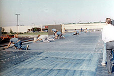
Figure 4. Application of a fully adhered single-ply membrane.
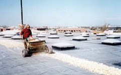
Figure 5. Application of aggregate ballast over a single-ply membrane.
2. Ballasted: The membrane is loose-laid over the substrate and then covered with ballast to resist wind uplift. Ballast can either be large aggregate (for example, 1-1/2 or 2-1/2 inches nominal diameter, depending upon design wind speed), concrete pavers weighing 18 to 25 pounds per square foot (psf), or specially designed lightweight interlocking concrete pavers weighing approximately 10 psf [49 kg/m²]. Ballasted systems are limited to a maximum slope of 2:12. Ballasted systems should conform to ANSI/SPRI RP-4. Finally, ballasted systems should not be used in high wind or hurricane areas because the ballast tends to become airborne, causing massive damage to adjacent buildings.
If crushed aggregate is specified, a stone-protection mat between the membrane and aggregate should be specified to avoid puncturing the membrane. A stone-protection mat is also recommended when smooth aggregate is used because some sharp fragments are often among the smooth aggregates. Also, aggregates sometimes fracture into very sharp pieces after they have been installed. It is also a conservative practice to specify a mat to protect against abrasion and puncture from fragments during paver installation. A somewhat thinner mat is normally sufficient for paver-ballasted jobs.
NRCA recommends designers consult specific membrane manufacturers' recommendations for their acceptable aggregate types and ballast application rates.
Generally, loose-laid, ballasted roofing systems are not recommended, or at least, discouraged, for three reasons: 1) a leak is very difficult to locate because the water runs freely in numerous directions and for longer distances under the loose-laid membrane; 2) the membranes tend to pull at their perimeter ties, raising and stretching the membrane around the parapet copings and base flashing areas where the membrane then thins and punctures easily; and 3) the ballast can puncture the roof membrane. For these reasons, fully adhered systems or mechanically attached systems are preferred over loose-laid.
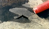
Figure 6. This EPDM membrane was cut by a piece of aggregate. Installation of a stone-protection over the membrane would avoid aggregate punctures. These types of punctures are very difficult to find. The end of a pen shows the scale.

Figure 7. The stone in the center of the photograph shattered into several sharp pieces after installation on a ballasted single-ply. Installation of a stone-protection over the membrane would avoid punctures and sharp fragments such as these.
3. Mechanically Attached: The membrane is loose-laid except for a discrete rows of fasteners. There are a variety ways of fastening and fabricating seams with this method, as described in A Guide for the Wind Design of Mechanically Attached Flexible Membrane Roofs which is available from the National Research Council Canada.
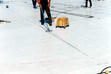
Figure 8. This mechanically attached single-ply membrane uses the "bar-over" attachment method. After installation of the membrane, a batten bar is placed over the membrane and screwed to the deck. A stripping ply is then installed over the bar.
Mechanically attached systems may not be suitable for buildings in high wind zones. Specify an air barrier on the deck (in conjunction with a vapor retarder in cold climates with high humidity interiors or with membranes or on new concrete decks) to prevent wind pumping (see discussions above under air barriers and vapor barriers).
To avoid tear propagation in the event that the membrane is torn, it is recommended that only reinforced membranes be specified for this attachment method.
Because of the mechanical stresses focused on the edges of the sheet and the air pumping which acts to pull interior air into the roof assembly and cause condensation problems, mechanically fastened membranes are not typically considered the best choice.
4. Electromagnetic Induction Welding: A thermoplastic roof membrane is bonded to fastening plates without membrane penetration or a fastener line at membrane sheet seams. The fastening plates are factory coated with the same material as the roofing membrane and an induction welder tool is used to bond the roof membrane to the plates from above the membrane.
5. Loose-Laid Air-pressure Equalization System: The membrane is fully adhered around the roof perimeter, but elsewhere the membrane is only loose-laid. This system should only be used over an air-impermeable roof deck or over an air barrier. To compensate for minor air leakage between the membrane and the deck/air barrier, air-pressure equalization valves are installed at prescribed intervals. The valves are one-way: they allow air underneath the membrane to vent out, but outside air is prevented from flowing through the valve and underneath the membrane. As with mechanically attached systems, it is prudent to only specify reinforced membranes for this attachment method. This type of system is susceptible to wind blow off if the vents fail to operate or future roof penetrations are cut through the deck/air barrier and left unsealed. These systems are typically not recommended due to shifting of the insulation board that commonly occurs and the difficulty in detecting leak locations due to the free flow of water underneath.
6. Protected Membrane Roof (PMR): See the Modified Bitumen (MB) section above.
Single-Ply Roofing Materials
Thermoplastic Single-plies
Thermoplastic materials do not cross-link, or cure, during manufacturing or during their service life. Field-fabricated seams are typically welded with robotic hot-air welders. Hand-held, hot-air welders are used to weld seams at flashings and penetrations. Thermoplastic membrane seams are typically extremely reliable when properly installed, resulting in a very low incidence of seam failures. These sheets are normally around 5 to 12 feet wide [1.5 to 3.6 m]. Some manufacturers weld the sheets together in the factory to form large sheets that are then welded together on the roof.
Primary membrane types in this category are:
Polyvinyl chloride (PVC): PVC membranes are among the oldest single-plies still available. If in contact with polystyrene insulation, the polystyrene will cause the plasticizers in the membrane to leach out. To avoid such membrane embrittlement, a separator sheet needs to be installed between the membrane and the polystyrene. To avoid membrane damage, a separator is also needed to isolate PVC from asphalt and coal tar products. The ballasted attachment method is not recommended because fine dust particles from the ballast or particulate fall-out from the atmosphere may leach plasticizers from the membrane. PVC membranes are available in a wide variety of colors and can even be printed with building names and logos. This membrane is sometimes selected for steep-slope roofs where a strong or unique color is desired. PVC is naturally a brittle material and must be modified with plasticizers to be suitable for roofing. Some early formulations of PVC suffered from plasticizer leaching out over time and experienced catastrophic failures. Select PVC membranes that have been manufactured for many years to verify their stability.
PVC and PVC alloys are resistant to animal fats and grease and are a good choice for roofs with kitchen exhausts.
PVC Alloys or Compounded Thermoplastics (also referred to as PVC blends): These membranes are related to PVC membranes. They are primarily compounded from PVC, but they have additional polymers that provide somewhat different physical properties. Only a very small number of manufacturers make these products. The primary types of membranes in this category are: copolymer alloy (CPA), ethylene interpolymer (EIP) and nitrile alloy (NBP).
Thermoplastic Polyolefin (TPO): TPO membranes are a relatively new roof membrane in the commercial roofing market and have seen several reformulations in the past decade. They are typically white in color and, as a thermoplastic, the seams are heat welded. Since they are new, long-term performance is unknown at this time.
TPO is the latest thermoplastic membrane introduced into the marketplace. It was commercialized in North America in the early 1990s. It is formulated from polypropylene, polyethylene or other olefins. Unlike PVC and PVC blends, TPO membrane do not rely upon plasticizers for flexibility, so embrittlement due to plasticizer loss is of no concern. TPO membranes are typically white, and are available in sheet widths up to 12' [3.6 m]. NRCA suggests designers specify 60-mil-thick or thicker TPO membranes.
Ketone ethylene ester (KEE): This membrane is also referred to as a tripolymer alloy (TPA), and the polymer is known by the trade name of Elvaloy. KEE sheets are similar to PVC.
Thermoset Single-Plies
Thermoset materials normally cross-link during manufacturing. Once cured, these materials can only be bonded together with a bonding adhesive or specially formulated tape. Primary membrane types in this category are:
Ethylene Propylene Diene Monomer (or Terpolymer) (EPDM): EPDM is a synthetic rubber sheet. As of 2005, EPDM enjoys the largest market share of the single-plies in service in North America. EPDM membranes are extremely resistant to weathering and they have very good low-temperature flexibility. However, EPDM is susceptible to swelling when exposed to aromatic, halogenated, and aliphatic solvents, and animal and vegetable oils such as those exhausted from kitchens. On portions of roofs where the membrane may be exposed to these materials, an epichlorohydrin membrane can be specified over the EPDM as discussed below. EPDM membranes are suitable at airport buildings, provided liquid fuel is not spilled on the membrane.
The sheets are typically available in widths of 10, 20 and 45 or 50 feet [3, 6 and 14 or 15 m], and lengths up to 200 feet [61 m]. Hence, on large roofs with very few penetrations, this type of membrane can be very economical to install. Most EPDM sheets are black, although white sheets are available. White sheets, however, are not nearly as resistant to weathering as black sheets. EPDM is typically non-reinforced. Note that reinforced sheets can begin to delaminate very quickly if water gets to the scrim because of abuse or simply from wear. Therefore, reinforced sheets are only recommended for mechanically attached and loose-laid air-pressure equalized applications. Reinforced sheets also offer some increased resistance to puncture and tearing when used in fully adhered and ballasted applications, where non-reinforced sheets are vulnerable to physical damage, especially if rounded, graded to 3/4" minimum size, river-washed ballast is not used. If a rigid insulation cover board is included as a substrate the non-reinforced sheet is preferred.
In fully adhered applications, typically a contact adhesive is applied to the substrate and the sheet. After the adhesive dries, the sheet is mated with the substrate. Another method of application uses fleece-backed EPDM, which is set in low-rise sprayed polyurethane foam adhesive. As there may be issues with a fleece-backed system set in asphalt, designers are advised to consult with the manufacturers before specifying or detailing fleece backed system with asphalt.
Field seams are formed using either a liquid-applied adhesive or specially formulated tape. The latter is recommended. Although tapes offer performance advantages over liquid-applied adhesives, the contractor still needs to exercise care in cleaning the EPDM prior to tape application, priming the EPDM and diligently executing the seam work as recommended by the manufacturer.
EPDM roof membranes provide predictable serviceability in roof systems in all climates. The minimum sheet thickness should be 60-mils if reinforced and 90-mils if unreinforced. All lap seams shall be fabricated with 6-in. (150 mm) seam tape and stripped-in with self-adhering, semi-cured EPDM cover strips.
EPDM sheets are resistant to the effects of UV radiation and are very durable. Seaming technology and adhesives have improved reliability with the use of tape-applied adhesive. Tape applied seams should be used. Properly constructed EPDM systems are now providing 30 years or more of service life.
Epichlorohydrin (ECH): This sheet is similar in appearance to EPDM. ECH, however, is resistant to hydrocarbons, solvents and many greases and oils, so it can be used in areas of the roof that are exposed to chemical discharges that are harmful to EPDM. Because of its permeability, the ECH manufacturer recommends placing ECH over an EPDM membrane. Because it is so specialized, ECH is seldom used. Only one manufacturer produces it in North America.
Pros and Cons for Single-Ply Roofing
| PROS | CONS |
|---|---|
| Highly productive installation. | Thinner sheets are easier to puncture, May not be good choice for roofs with extensive mechanical equipment requiring maintenance. |
| Easily repaired and modified. | Due to high price-point pressures, manufacturers may offer materials and details that are not as reliable as owners may require. |
| Better appearance compared to BUR and MB | Cold fluid adhesives may have high VOC content. |
| Available with a variety of cool coatings. |
Mesh Reinforced Elastomeric Coatings (MREC)
Figure 9. Mesh reinforced elastomeric coating installation.
Mesh Reinforced Elastomeric Coatings are gaining market share in today's roofing world. Composed typically of acrylic elastomeric and polyester reinforcing mat applied in multiple layers for a final dry film thickness of 52 mils, these systems have changed the traditional roof repair and replacement paradigm. Eliminating the environmental aspects of removing an old 4 ply BUR, the MREC allows cleaning of aggregate, and application of 52 mil system with predictable 15–20 year life at a fraction of traditional replacement cost.
Sprayed Polyurethane Foam (SPF)
SPF is a very unique type of roof system. The membrane is constructed by spraying a two-part liquid onto a substrate. The mixture expands and solidifies to form closed-cell polyurethane foam. NRCA recommends SPF intended for use as a roof system to have a minimum density of 2.8 pounds per cubic foot and a minimum compressive strength of 40 pounds per square inch.
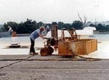
Figure 10. This SPF roof is being installed with a robotic sprayer.
The substrate can be the roof deck, an existing roof membrane (provided the existing roof is suitable for re-covering), gypsum board, or rigid insulation. The foam is applied with hand-held sprayers or with robotic sprayers. Each pass (or lift) of foam is typically between 1/2 to 1-1/2 inches [13 to 38 mm] thick. If a greater total thickness is desired, two or more passes are normally required. The total thickness of the foam can be easily varied to provide slope for drainage.
A protective surfacing is required for long-term performance of an SPF roof system. A protective coating must serve multiple functions in protecting the underlying SPF and should be selected from coatings that have been specifically designed for SPF and have a proven history of performance when used over SPF. Protective surfacings are a part of SPF roof systems to provide weatherproofing, ultraviolet (UV) protection, mechanical damage protection, and fire resistance. This is typically accomplished by using one of the following coatings.
Coatings for Sprayed Polyurethane Foam
Acrylic Coating: This is the least expensive of the coatings, and generally offers the shortest service life (although the best acrylics can last longer than some of the polyurethane coatings). Acrylic coatings should be used as part of an SPF roof system in order to comply with ASTM D6083. With acrylics, re-coating is required about every 10 to 15 years, depending upon the quality of the coating material, application, and climate. They are typically white.
Polyurethane Coating: When properly formulated, this coating offers long service life. This can be the toughest coating available in terms of impact and tear resistance, although a wide range of physical properties is available in this product category. Both one- and two-part coatings are available. One-part coatings are typically gray, although white is available. Two-part coatings are typically white. Single-component polyurethane coatings should be used as part of an SPFP roof system complying with ASTM D6947.
Silicone Coating: Silicone coatings offer exceptionally good weather resistance and long service life. These coatings are typically offered in a gray color, as silicone coatings pick up dirt (if a white silicone is installed, it will soon become gray). More than other coatings, silicone coatings are prone to being pecked by birds. To avoid the pecking, granules are commonly broadcast into the coating while it is wet. Silicone coatings should be used as part of an SPF roof system complying with ASTM D6694.
Mineral Granules: Mineral granules (similar to those used to surface asphalt shingles) can increase the durability of a coating and provide greater slip-resistance to persons on the roof. Course sand can also be used for these purposes. Granules or sand are broadcast into a coating while it is wet. If granules are used, they should be selected and installed according to the coating manufacturer's recommendations.
Aggregate Surfacing: Properly formulated and installed SPF is quite resistant to liquid water. Therefore, aggregate of the size used on BUR systems can be applied directly over the foam. At parapets and equipment curbs, one of the previously described coatings is applied on the vertical surfaces and out several inches onto the field of the roof. Because water vapor can migrate through the foam, the aggregate surfacing option should not be specified in situations where the annual net vapor flow is downwards. As with aggregate-surfaced BUR, consideration should be given to aggregate blow off.
Other Considerations
The worker performing the spraying must be very skilled and knowledgeable. If the qualifications of the contractor and the spray mechanic cannot be reasonably assured, it is prudent to specify an alternative system. Installation of SPF roofing is especially sensitive to temperature, relative humidity, wind speed, and other environmental factors.
SPF systems have several important attributes. Besides readily lending itself to complex roof shapes, SPF roofs are exceptionally thermally efficient, since they do not have mechanical fasteners or insulation board joints, which create thermal bridges. Also, field research has demonstrated that they have exceptionally good wind resistance. Notably, an SPF roof is not in imminent danger of leaking if the coating is weathered away or ruptured or the aggregate surface is displaced, provided that the penetration does not extend all of the way through the foam (which is generally unlikely). Damaged areas should be promptly repaired however to prevent further damage to the underlying foam due to UV exposure. This attribute is in stark contrast with the other low-slope system options, in which leakage typically occurs if the membrane is punctured.
Standing-Seam Metal Roofing (SSMR)
Standing-seam metal roofs are often used for their appearance. However, it is extremely difficult to make all of the metal-to-metal joints permanently waterproof.
SSMR systems are either hydrostatic that are designed and constructed to be totally water resistive (like a roof membrane) or hydrokinetic that is not totally resistive to water intrusion and rely on slope to shed water.
There are two primary approaches to low-slope metal roofs:
1. Hydrostatic: With hydrostatic systems the panels have standing seams, which raise the joint between the panels above the water line. The seam is sealed with sealant tape or sealant in case it becomes inundated with water backed up by an ice dam or driven by wind.
Most hydrostatic systems are structural systems (e.g., the roof panel has sufficient strength to span between purlins or nailers). A hydrostatic structural panel (which cannot span between supports) may be specified if a solid deck is provided.
2. Hydrokinetic: Most standing seam metal roofing panels are hydrokinetic, or water shedding, and therefore require a slope greater than 3:12 (25 percent).
Metal Panels
Metal panels are not typically thought of as options for low-slope roofs. Some metal panel systems, however, can be used on very low-slopes. Although some manufacturers tout their systems as being suitable for slopes as low as 1/4:12 (2 percent), NRCA recommends a minimum slope of 1/2 inch per foot as the minimum design slope for hydrostatic roof assemblies and 3 inches per foot as the minimum design slope for hydrokinetic systems. The greater the slope, the more reliable the leakage protection.
This section addresses metal panels suitable for use on slopes of 3:12 (25 percent) and less. These panels can also be used on slopes in excess of 3:12. See Steep-Slope Roofs for metal panels that are only suitable for slopes greater than 3:12.
When installed on low-slopes (particularly slopes approaching 1/2:12 (4 percent) or less) a metal panel system needs to provide water resistance all across the roof surface. Thus, low-slope metal panel systems should be designed and installed with the intent of making them membrane-like. To achieve this, the panel joints must be soldered or sealed together with sealant tape or sealant, or both. Also, fasteners that penetrate the panel at end-joint splices or flashings must be sealed with gasketed washers. In addition to making all of the metal joints watertight, they must remain watertight while undergoing extensive movement from thermal cycling. Over time, thermal movement of the metal can tear through fastener gaskets and enlarge holes at fasteners.
One should be cautious about using continuous sheet metal in a flat roof situation. Sheet metal is prone to wider, more extreme temperature swings because of its dense nature as a material, especially in the sunlight on a roof. This will cause significant expansion/contraction movements in the sheet metal surface. The movements themselves are difficult to manage, but combined with necessary roof penetrations for vents, drains, curbs, and wall corners, which bind the inevitable movement, tears or seam breaks in the sheet metal are highly likely. Consider employing sheet metal in flat roofs only where there are no penetrations and the movements can be accommodated. It is more difficult to achieve a reliable and long-lasting watertight system on a low-slope roof with metal than it is with the other low-slope membrane materials.
Galvalume-coated sheet steel or aluminum panels are typically specified for low-slope standing seam panels. On historic projects copper, terne-coated copper, or terne-coated stainless steel may be used.
For corrosion protection on steel panels, current practice is to specify 55% aluminum-zinc alloy (commonly known by the trade name Galvalume). Until the late 1990s, unpainted aluminum-zinc alloy panels had a factory-applied lubricant to facilitate roll forming. The lubricant eventually weathers away, but installation smudges and fingerprints result in uneven appearance for a while. A thin clear acrylic coat can be specified to provide a more even appearance and show the effects of weathering more gradually, as the acrylic weathers away. Acrylic-coated Galvalume is sold under trade names such as Galvalume Plus and Acrylume.
Factory-coated low-slope panels are recommended. There are several finish options. The most common factory-applied coil coating is polyvinylidene fluoride (PVDF), commonly known by the trade names of Kynar and Hylar. PVDF is typically specified since if offers a large range of colors and is extremely resistant to color change over time. Painting can also be specified when a high emissivity is desired.
Internal gutters and parapets at the eaves of low-slope metal roofs should be avoided, as it is less problematic to have the water flow over the end of the panels and fall directly to grade or drop into an external gutter that is below the plane of the panels.
Some panels have snap-together seams, while others are mechanically seamed with an electrically powered mechanical seaming tool. On slopes of 1:12 (8 percent) or less, it is recommended that mechanically seamed panels be specified.
There are two basic types of standing-seam panel profiles, the trapezoidal rib and the vertical rib. Because of its appearance, the trapezoidal rib panel is typically used on industrial buildings and warehouses. The trapezoidal panel is difficult to make watertight at hips and valleys.
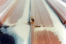
Figure 11. Unless very well designed and installed, wind-driven water can infiltrate end-joint splices. Full-length panels eliminate this problem area.
In addition to the standing seam panels, through-fastened panels (also referred to as R-panels) with exposed fasteners are available for low-slope systems with slopes in excess of 2:12 (17 percent). They should be considered hydrokinetic systems. This is a relatively inexpensive system. It has largely been replaced by standing-seam systems, which eliminate leakage problems that are often associated with exposed fastener systems. Other exposed fastener systems include corrugated panels and 5-v crimp panels.
To avoid leakage problems at panel end-joint splices, it is preferable for the panels to be continuous from eave to ridge. If panels are quite long, job-site roll forming may be necessary. However, full-length panels are sometimes impractical and can expand and contract 1" or more, making detailing very difficult.
The Metal Roof Systems Design Manual by the Metal Building Manufacturers Association provides further guidance pertaining to metal roof systems.
Flat seamed structural panels
This is also a hydrostatic, or water barrier, system. This traditional system requires a solid substrate. It also requires the use of metals that can be soldered, such as copper. This type of system is labor-intensive. Hence, it is relatively expensive. Because it demands diligent workmanship to provide long-term water protection, it is recommended that this system not be specified unless done so for structural restoration or compatibility purposes.
Liquid-Applied Roof Membranes
Liquid-applied roof membranes are more widely known to be used as waterproofing systems but have gained in popularity as roof systems, especially in reroofing situations and in PRM Assemblies. However, if a liquid-applied roof membrane does not have reinforcement, it typically is considered a coating system. A reinforced liquid-applied roof membrane is considered by NRCA to be a roof system. The most common and reliable liquid-applied systems are the hot-applied rubberized-asphalt systems with uncured neoprene reinforcement.
Liquid-applied roof membranes generally are installed in 70-mil, 80-mil or 90-mil finished thicknesses but can be as thick as 115-mil in some applications. Consult the specific manufacturer for recommended thicknesses. Liquid-applied membrane roof systems typically are reinforced with polyester reinforcing fabric or fleece.
Steep-Slope Roof Coverings
The following roof coverings are commonly used on steep-slope roofs. These coverings are water shedding, rather than waterproofing. Special underlayment provisions are required when slopes are relatively low. The NRCA Roofing Manual provides underlayment guidance.
Metal Panels and Shingles
When used on slopes greater than 3:12 (25 percent), hydrokinetic or water-shedding panel systems may be used. Hydrostatic (water barrier) systems may also be used. Structural panels may be specified if a solid deck is provided. If a solid deck is not provided, structural panels need to be specified.
Metal shingles are also available in a variety of metals and designs. The performance varies greatly depending upon the product selected.
Asphalt Shingles
Shingles are available with either fiberglass or organic reinforcement. Fiberglass-reinforced shingles provide greater fire resistance and are therefore recommended. Asphalt shingle products are typically tested and classified for impact resistance according to UL 2218. This standard provides for four classifications: Class 1, Class 2, class 3 or Class 4. Class 1 provides for the least measured resistance of impact resistance, and Class 4 provides for the relatively greatest level of impact resistance. NRCA suggests designers consider specifying asphalt shingles with Class 3 or Class 4 in regions prone to large-sized hail.
In addition to the traditional three-tab design, laminated (structural) shingles are available where a different appearance is desired. Product standard ASTM D3462 has limited criteria to distinguish various products in the marketplace. Therefore, warranty duration is normally used to attempt to distinguish commodity products from those that offer longer service life. However, the warranty duration is not necessarily an indication of performance. Shingles with a minimum warranty of 25 years are recommended.
Slate
Natural slates have the potential to offer several decades of service life. However, slate is heavy and very expensive. If slate is specified, a very durable underlayment is recommended, so that it does not prematurely degrade.
Specifiers are cautioned that synthetic materials are often marketed as slate. Some of these products are made from slate particles, while others are made from polymers or other materials. Synthetics should not be expected to offer a service life equivalent to natural slate.
Tile
Tiles can either be made from clay or concrete. Tiles typically can be expected to offer a longer service life than asphalt shingles. However, tiles are heavy and more costly than shingles.
Applications
After identifying the project's requirements a roof system should be selected that optimally responds to an integration of the project's requirements and the system selection criteria discussed in System Selection Criteria below. After the roof system is selected, drawings and specifications are prepared to communicate the roof designer's design concept to a professional roofing contractor. This section also covers warranty considerations, key elements of drawings and specifications, and construction contract administration.
System Selection Criteria
Roof System Selection
For most roofs, several different types of systems could serve quite well. But some roofs have unique characteristics that lend themselves to perhaps only a few systems. In order to select the most appropriate system for a project, ideally the designer should have a good understanding of the material and system options described in the Description section. On large (>15,000sf) and significant projects the designer should be a registered engineer, architect, or consultant that derives their principal income from roof design. Note that roofing system manufacturers specifically state that they do not design roof systems.
In the context of this section, system selection refers to selection from the primary system types discussed in the Description section (such as BUR, modified bitumen, single-ply, sprayed polyurethane foam, metal panels, asphalt shingles, slate, or tile), as well as the selection of membrane materials within system types (such as type of modified bitumen, type of single-ply membrane, type of surfacing on an SPF, type of metal panel profile, or type of shingle or tile), and where applicable, the attachment configuration (fully adhered, ballasted, mechanically attached, PMR, or loose-laid air-pressure equalized).
Establish Criteria
- Factory Mutual (insurance underwriters') requirements.
- Structural engineer to do wind uplift analysis per ASCE 7.
- Required R-value/u-factor for energy code compliance.
- Cool roof: yes or no.
- Aesthetics: can the roof be seen from above?
- Interior and exterior temperature/humidity parameters.
- Owner's risk tolerance (i.e. data center versus common commercial space).
- Owner's ability to maintain the roof.
- Roof access to public?
- How much mechanical equipment on roof?
- Need for early enclosure with temporary roof to facilitate construction?
- Local trade practices and preferences.
- How much subsequent construction over low roofs while working on walls above?
- Ability to reach the roof in the future such as in high-rise situations.
- Requirements for fire resistance rated assemblies.
- Smoke developed/flame spread criteria.
- Hail resistance.
- Hurricane zones: high winds and elimination of small missiles (ballast).
- Owner's expectation for warranty coverage: will the owner expect and pay for a warranty that extends all the way to the predicted wind speed.
- Life-cycle costing.
- Where is drainage and what type? Is the structural deck sloped?
- How is secondary (overflow) drainage to be accomplished?
- Design of parapets.
- Available height for base flashings.
- Presence of animal fats or other exhausts that can harm some membranes.
- Presence of other contaminants, such as jet fuel for roofs at airports that can damage some membranes.
- For re-roofs: there are many more criteria
With an understanding of the available system options, consideration of the following technical and non-technical criteria can lead to the selection of the most appropriate system and details for a project.
- System demise
- Contractor familiarity and availability
- Maintenance intensity
- Technical considerations
- Available technical support from manufacturer.
- Veracity of manufacturer's training programs for roofing installers.
- Coverage and fairness included in manufacturer's warranty.
- Types of roofs in vicinity
- Cost
- Warranty
- Implications of sustainable roof design
It is critical that the selected system sufficiently satisfy all of the criteria. Specific system selection recommendations are given later below.
Design Life
Roof system design life should be a starting point in the selection of roof systems. Most buildings utilize a minimum 20-year roof design life. Since many roofing systems have not been in production for 20 years, the designer should consider proven systems as a first step in obtaining roof design life.
System Deterioration
Determining the factors that will cause the roof system to deteriorate is necessary in system selection. For example: 1) Is the project located in an area that experiences frequent and damaging hailstorms? 2) Does the roof have numerous HVAC units, the service of which will generate perpetual abusive foot traffic? 3) Will the roof be exposed to intense solar radiation throughout most of its life? 4) Is the roof accessible for repair? 5) Is there a kitchen hood that can damage the roof membrane? 6) Are there industrial uses or labs that exhaust acidic vapors? 7) Are there other toxic exhausts? 8) Etc.
In some cases, one factor will likely cause accelerated deterioration. In other cases, perhaps two or three factors may be nearly equally as likely to end the roof's life. After identifying the likely cause(s) of deterioration, it is necessary for the roof designer to select a system with characteristics that can combat the destructive force(s).
Contractor Familiarity and Availability
Proper application is crucial to the long-term success of a roof. During the system selection process, the following should be considered:
-
Are contractors in the vicinity of the project site familiar with the system being considered? If not, either a system should be selected that the local contractors are familiar with, or a contractor should be brought in from outside of the project vicinity. It is important to avoid having a contractor install a system that he or she is not extremely familiar with.
-
It is preferable to select a system that can be installed by contractors who have an office relatively close to the project site. By doing so, the contractor will be familiar with local conditions such as historical weather conditions during the projected application period and logistics.
Maintenance Intensity
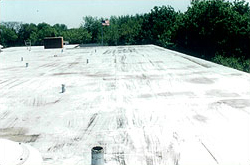
Figure 12. This APP modified bitumen was field-coated. The coating is weathering away as expected. If a system with a field-applied coating were to be specified, periodic re-coating would be required throughout the roof's life. If re-coating is not performed, the roof's service life and or other properties such as fire resistance will be reduced. Consideration should be given to applying a mesh-reinforced elastomeric coating (MREC). Application of such a coating here can eliminate waste and improve durability.
Because of uncertainties pertaining to future budgets for periodic maintenance, a roof system should be selected that has limited maintenance demands. Therefore for example, a system that requires re-coating more frequently than every 15 years is not recommended. Hence, rather than specify a modified bitumen membrane with a field-applied coating, a granule or foil-surfaced membrane is preferable to avoid future re-coating costs (see Figure 12).
Regional Considerations
Often there are regional requirements where the new building will be constructed, it is recommended that the roof designer request information on the type of roofs in the region, number of roofs within each system type, and the experience that the industry has had with the various types. If a specific system has been a good performer, it is probably best to use that system on the upcoming project, unless the new project has unique characteristics that another system would be better able to accommodate. Also, if the Owner has periodic inspection, maintenance, and minor repairs performed by in-house maintenance personnel, one advantage of keeping with the same type of system is that they will not have to become familiar with another system type.
Technical Considerations
Most of the topics discussed in this chapter are technical in nature. Many of those considerations strongly influence the system selection. The considerations that influence system selection vary from job to job, depending upon the project location and requirements. When selecting a system it is important for the roof designer to determine whether the proposed system should more than just meet the minimum requirements. For example, if external fire resistance is particularly important for a project due to a strong threat from wildfires, then rather than just specify a system that meets Class A fire resistance, a better choice would be a system that has enhanced fire resistance, such as a paver-surfaced system. In northern climates consideration should be given to the potential for falling ice and snow. See the Resource Page Considerations for Building Design in Cold Climates.
Cost
Many select a roof system primarily on initial cost. Although cost is an important element of a project, when cost is a governing factor in system selection, typically there are ramifications. If a less expensive system is selected, invariably something suffers in comparison with the system(s) that fell from consideration because of the greater cost. The cheaper system generally will not have the reliability or durability of other systems; it may be more maintenance intensive or it may not be as energy efficient. Over the life of the roof, the system with the lowest initial cost often is more expensive than other options that were discarded because of their higher initial cost.
In evaluating cost, it is important to look at the life-cycle cost (LCC). In addition to the initial construction cost, LCC includes energy consumption (for building heating and cooling), maintenance, repairs, length of service life, and disposal at the end of the roof's life. Of these factors, the most difficult to assess is the design service life. A common service life to be expected is 20 years.
The service life can have a dramatic impact on the LCC analysis. For example, if a 40-year service life is assumed, but the roof fails after 15 years, the true roofing costs will be much higher than calculated. Lack of good data on design service life is often a significant limitation to developing a reliable LCC. It is difficult to have confidence in a manufacturer's claim of, for example, a 30-year life for products that have been in the marketplace for only a few years. Accelerated aging testing is of limited help, as it has not progressed to the point where credible estimates of service life prediction can be made. The selection of a predicted service life should be conservative. For most low-slope systems, use of a service life in excess of 20 years should only be done with caution, evaluation, and justification.
For most projects, the costs associated with eventual tear-off and disposal are seldom considered. Because some systems are inherently more difficult to tear-off than others, LCC analysis should consider this issue. Also, it may be possible to salvage or reuse some of the system components. For example, with a PMR, it would be reasonable to assume that much of the ballast and insulation could be reused on the replacement roof.
Where the cost to access and/or repair a roof are very high, or the risk of failure results in an excessively expensive repair due to landscaping or difficult access, it is important to make the investment in the highest quality, most durable, long-term roof system available. The later costs of repair are usually enormous relative to, and in comparison to, first-cost investment difference for the highest quality roof.
Although there are difficulties and limitations with the LCC approach, economic decisions based on LCC are preferable to those that only consider initial system cost. ASTM E 917, Standard Practice for Measuring Life-Cycle Costs of Buildings and Building Systems provides further information on LCC.
Implications of Sustainable Roof Design
Sustainable roof design should be considered on most roofing projects today. If an emphasis on sustainable roof design is desired, sustainable design criteria can become major factors in the selection process, depending upon the degree to which sustainability is pursued. At the very least, the selected system should be thermally efficient, with consideration given to R-value, reflectivity and emissivity. And for those buildings that are intended to have a service life in excess of 20 years, a system with enhanced durability should be selected to reasonably maximize the life of the roof to the extent that the budget allows.
Sustainability goals (among others):
- Minimize the burden on the environment.
- Conserve energy.
- Extend roof lifespan.
- Reduce carbon footprint.
- Reduce heat-island effect.
See Sustainability of the Building Envelope, Cool Metal Roofing, and Extensive Vegetative Roofs for further information on sustainable design considerations.
Specific Roof System Selection Recommendations
Roof system selection can be complex and challenging. Selection should start with if the project is a new or existing roof. This step is necessary to proceed with proper system selection as it determines roof system type. New construction allows better choice in the roof system selection and should begin with designing steep slope systems >3 in./ft. when possible, followed by low sloped <3 in./ft. where required. Generally, when a building least dimension is 75' or less, a steep-sloped system should be selected over a low-sloped system.
Guidance for Low slope and Steep Slope Systems
-
Extend Roof Lifespan
- Employ designers, suppliers, contractors, trades people, and facility managers who are adequately trained and have the appropriate skills.
- Select materials that are sold by manufacturers that provide robust technical support, training, and oversight of their products. Materials sold as commodities without technical support can lead to problems.
- Adopt a responsible approach to design, recognizing the value of the robust and durable roof.
- Provide effective drainage to avoid ponding. Utilize 1/2" per ft. if possible. Use crickets to direct water to drains, depress drains in 4 ft. square sumps, 1-1/2" deep.
- Raise perimeter base flashing seams and details up out of the main roof plane and out of standing water with tapered edge strips.
- Minimize the number of penetrations through the roof.
- Ensure that high maintenance items are accessible for repair or replacement.
- Monitor roofing works in progress and take corrective action, as necessary.
- Control access onto completed roofs to reduce punctures and other damage, providing defined walkways and temporary protections.
- Adopt preventative maintenance, including periodic inspections and timely repairs.
-
Minimize Burden on the Environment
- Use products made from raw materials whose extraction is least damaging to the environment.
- Adopt systems and working practices that minimize waste.
- Avoid products that result in hazardous waste.
- Recognize regional climatic and geographical factors.
- Use products that can be reused or recycled, where possible.
-
Conserve Energy
- Optimize the real thermal performance, recognizing that thermal insulation can greatly reduce heating or cooling costs over the lifetime of a building.
- Keep insulation dry during construction to maintain thermal performance and durability of the roof.
- Consider embodied energy combined with energy savings over lifespan.
- Consider the roof surface color and texture with regard to climate and the effect on energy and roof system performance. A tool for doing this is the DOE Cool Roof Calculator.
- Use local labor, materials, and services wherever practical to reduce transportation, although this a low consideration compared to how well they perform and if they save energy over the long term.
Warranty Considerations
Roof designers often incorrectly give considerable weight to a manufacturer's warranty when considering a roof system and a specific manufacturer. Many limitations are associated with most warranties. The warranty itself should not be the basis for selecting a system or a manufacturer.
Warranties do not stop or protect against leaks. They do not entitle a building owner to a replacement roof if there are manufacturing defects in materials. They do not provide for proactive replacement if a roof is clearly failing and degrading but still not leaking. They do not cover any consequential damages to other building components or contents of the building. They do not provide any coverage for lost time or productivity resulting from a leak. Furthermore, they do not ensure that damage caused by hail or wind, or another type of damage will not occur. Rather, a warranty most typically provides for limited repairs of the roof membrane only after a leak occurs. Legally, a warranty defines specific rights and obligations of the building owner and warrantor. It includes remedies and exclusions. If the warrantor is out of business when a problem covered by the warranty is experienced, the warranty often becomes a useless piece of paper.
Since the 1970s, many warranties have become marketing tools rather than true reflections of demonstrated roof system performance. It is common to see 20-year warranties on roof systems that have only been in the marketplace for a few years. When architects rely on warranties for performance, rather than paying attention to the factors that actually affect performance; the potential for premature failure dramatically increases.
When warranties are specified, the specification typically requires the warranty to be issued by the roof membrane manufacturer. It is recommended to specify that the warranty include both the roof membrane materials, other roof system components such as roof insulation, vapor retarders if used, fasteners, adhesives, flashings, and accessories. The warranty should cover the roofing contractor's workmanship. Material-only warranties are also available from manufacturers. In fact, it is nearly impossible to buy roofing membranes without at least a materials only warranty. However, these warranties are nearly useless. A manufacturer's warranty establishes a direct contractual relationship between the building owner and manufacturer. For low-slope systems, the length of coverage for a manufacturer's warranty is typically 5 to 25 years, with 10 years being the most common.
Warranties will be prorated in value unless they are clearly specified as a NO DOLLAR LIMIT (NDL) warranty. Prorated warranties provide very limited coverage in the later years of the warranty period just when the warranty coverage is most needed.
When involved with landscaped roofs, consider warranties that cover the cost of removing and replacing the overburden of the landscaping to access the roof. Reliable, hot-applied rubberized asphalt membrane roofing manufacturers will provide these.
Warranty Benefits
A warranty may have some merit if it means that the manufacturer will take steps to minimize the potential for future problems (such as reviewing the specifications and details and providing meaningful inspection during application). A warranty may also enhance the likelihood that a professional contractor will install a roof. However, rather than relying on a warranty to obtain a qualified contractor, designers should specify contractor qualification requirements as discussed in the next section.
If a problem that is covered by the warranty occurs, and the warrantor is still in business, the presence of the warranty may lead to a quick resolution of the problem. Virtually every warranty issued by a manufacturer covers repair of leaks caused by defective materials and workmanship (if the warranty is not for materials-only) provided that the cause(s) of the leakage is covered under the terms of the warranty. Without a warranty, the Owner might have to pursue legal action to obtain relief. Pursuing legal action may be too costly if the problem is small. Also, the presence of a warranty provides a direct avenue for the Owner to purse a claim with the manufacturer if the manufacture does not respond to a problem covered under the warranty.
Warranty Limitations
Warranties are normally prepared to limit the manufacturer's liability to a narrow scope of provisions rather than to provide protection for the building Owner. Warranties typically preclude claims based on other theories of liability, including negligence and breach of contract. In addition, warranties typically exclude the implied and express warranties established by the Uniform Commercial Code.
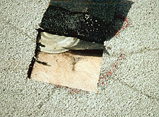
Figure 13. Although modified bitumen membranes offer good resistance to moderate sized hail when properly supported, this membrane was ruptured by hail as a result of compression of the insulation (it was not supported by a high-density cover board). Cap sheet granules were driven through the membrane and into the face of the insulation. Hail damage is typically excluded from manufacturers' warranties.
Warranties are almost always provided in standard language provided by the manufacturer's legal department and changes or deviations are extremely difficult. It is important to evaluate warranty coverage as part of the criteria to select the roofing material manufacturer before specifying. Most warranties contain several unfavorable provisions, the most significant being:
-
Exclusion of consequential damages (including damages to building interiors and contents, and business interruption)
-
Limitation of wind coverage to wind speeds that are typically well below the design wind speed prescribed in the building code. Coverage limited to very low wind speeds sometimes listed as only a "gale", which can later be interpreted to exclude any damages from winds exceeding 31 mph.
-
Exclusion of hail damage (see Figure 13)
-
Limitation of leak repairs to patching the membrane rather than removing and replacing wet insulation
-
Only the manufacturer can determine the applicability of the warranty
-
Inclusion of several provisions that could result in the building owner's inadvertent nullification of the warranty.
-
Unreasonable limitations on the owner's right to make emergency repairs without voiding the warranty.
-
Unrealistic requirements (often in very fine print) for meticulous record keeping and maintenance.
-
Complete voiding of the warranty if an "unapproved" roofer makes even a small modification.
Recommendations
Do not make a roof system or manufacturer selection on the basis of a warranty. Select a system for its suitability to the project, as discussed in System Selection Criteria above.
Do not automatically specify a warranty. Rather, select a system for its suitability for the project, as discussed in System Selection Criteria and Specific Roof System Selection above, and then determine if the Owner's best interests are served by a warranty.
If specification of a warranty is being considered, review the warranty section of NRCA's Low-Slope Roofing Materials Guide (or the Steep-Slope Roofing Materials Guide). Ensure that the manufacturer's standard language is not onerous BEFORE specifying that manufacturer. Make sure that the specified warranty includes:
- Defects in materials and defects for the entire roofing system with all materials and accessories included.
- Coverage up to the basic wind speed identified in the building code.
- No Dollar Limit coverage without prorating.
For government projects, if a warranty is desired, recommend that a Government attorney identify provisions of the manufacturer's standard warranty that are unacceptable, so that warranty provisions acceptable to the Government can be specified. The following are examples of changes to standard warranties that should be considered for all projects:
- Delete warranty language that takes away the Owner's rights
- Delete warranty language that excludes other rights and remedies
- Delete warranty language that sets a maximum dollar limit
- Delete or modify the unfavorable items listed above in "Warranty Limitations."
Key Elements of Specifications
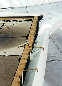
Figure 14. The wind load on this very wide gutter was transferred to the edge nailer, but the nailer attachment was not designed to account for the gutter uplift load. The nailer therefore lifted and caused a progressive peeling failure of the roof membrane.
After a suitable roof system has been selected, appropriate specifications and drawings need to be prepared to help ensure that the roof designer's design concept is understood and executed by a professional roofing contractor. The fate of many prematurely failed roofs is often set by poorly prepared documents (Figure 14). The importance of the designer's diligence in preparing specifications and drawings cannot be overemphasized.
The following elements are critical in communicating project requirements to the contractor:
- Specifications
- Roof Plan(s) and Details
Specifications
To produce good specifications, the roof designer should first acquire a suitable guide specification.
MasterSpec® is a reliable source of master specifications, which must be edited by experienced specification writers.
Also, the following Unified Facilities Guide Specifications (UFGS) are available:
Roof decks: 03 31 00.00 10 (cast-in-place concrete), 03 51 13 (pre-cast concrete), 05 30 00 (steel), 06 10 00 (wood)
Insulation: 07 21 16 (blanket [attic]), 07 21 23 (loose fill [attic]), 07 22 00 (rigid)
Built-Up Roof: 07 51 13
Modified bitumen: 07 52 00
Protected Membrane Roof (using a variety of membrane types): 07 55 00
Single-ply: 07 53 23 (EPDM), 07 54 19 (PVC)
Sprayed Polyurethane Foam: 07 57 13
Metal Panels: 07 41 13 (structural), 07 61 14.00 20 (steel standing seam roofing), 07 61 15.00 20 (aluminum standing seam roofing), 07 41 13 16 (copper roof system)
Flashing and sheet metal: 07 60 00 (flashing and sheet metal) and 07 62 10 (copper flashing)
Asphalt Shingles: 07 31 13
Slate: 07 31 26
Tile: 07 32 13 (clay and concrete)
After obtaining a guide specification, it is critical that the roof designer tailor it to the specific project. Information that is not applicable should be deleted. Applicable information should be adjusted if needed. Additional specification criteria should be added as necessary to suit the project. The following should be considered when developing Parts I, II, and III of the roof specifications:
Part I—General
-
Fire and Wind: Specify fire and wind resistance requirements. For wind uplift, specify the test method required to demonstrate required resistance (see Wind Safety Section 4.4 Roof Systems). (Note: For shingles, slate and tiles, normally the resistance for the corner areas is specified for use throughout the entire roof area because these products are typically used on small roof areas. For large slate and tile roofs, if there is sufficient cost savings, both corner, perimeter and field resistances can be specified.)
-
Submittals: Specify submittal of catalog data for all products, including installation instructions and, where applicable, maintenance and repair instructions. Specify submittal of samples only when necessary to evaluate the product. For example, it is normally not necessary to specify the submittal of an EPDM sample, because black sheets are typically specified and there is no factory-applied surfacing to evaluate. However, it may be appropriate to specify submittal of samples of a granule-surface SBS modified bitumen sheet in order to select the desired color and to qualitatively evaluate the granule coverage and embedment.
Specify that the following be submitted: Demonstration of specified contractor qualifications, manufacturer review letter, manufacturer inspection reports, certification reports demonstrating that materials comply with referenced standards, certificates of analysis (when specified), and documentation demonstrating enrollment in the MBMA certification program (when specified).
These items are discussed below:
-
Contractor Qualifications: Specify that the contractor have a minimum number of years of experience with the type of system specified (five years is usually a reasonable requirement). Also specify that the contractor is approved, authorized or licensed by the roof covering material manufacturer to install its product. For public bid work, this may make it difficult to find multiple manufacturers.
-
Manufacturer Review: Require the roof covering materials manufacturer to review the specification and drawings and advise in writing of their acceptance thereof, or to submit in writing their concerns and recommendations to resolve these concerns. Specify submittal of the review letter within a short time after contract award, so that if changes are needed there is sufficient time to develop them before the roofing begins.
-
Manufacturer Inspection: Require the roof covering materials manufacturer to inspect the roof application on the first or second day of application, and to perform an inspection upon completion of the application. Require submittal of the inspection reports.
-
Standards Compliance Certificates: To help ensure that products furnished to the project comply with referenced standards, specify that certificates demonstrating compliance be submitted.
-
Certificates of Analysis: For those products where certificates of analysis are available, consider specifying certificates of analysis that provide quality control test results for specific manufacturing lots (lot numbers are printed on the product package label).
-
Certification Program: If a metal roofing system is selected, consider specifying that the manufacturer be certified through the MBMA Metal Roofing Systems Quality Certification Program. Further information about the program is provided in the MBMA Metal Roofing Systems Design Manual.
-
Pre-roofing Conference: Specify a two-stage pre-roofing conference. The first conference should be held a few or several weeks prior to the start of roofing, depending upon job size and complexity. The second conference should be held just prior to application. The purpose of the conference is discussed later in this section.
Specify that the conference be attended by the general contractor, roofing contractor's project manager, superintendent (on large projects) and foreman, a representative of the roof covering materials manufacturer, and the mechanical, electrical, and lightning protection system (LPS) contractors if mechanical, electrical, or LPS work is associated with the roofing work. If a third-party inspection firm will be on the job, the inspector should also attend.
-
Quality Control Documents: If a BUR, modified bitumen, EPDM or sprayed polyurethane foam system is specified, specify application compliance with the applicable quality-control document co-produced by NRCA:
- Quality Control Guidelines for the Application of Built-Up Roofing
- Quality Control Guidelines for the Application of Polymer Modified Bitumen Roofing
- Quality Control Guidelines for the Application of Spray Polyurethane Foam-based Roofing
- Quality Control Guidelines for the Application of Thermoset Single-Ply Roof Membranes
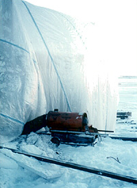
Figure 15. This BUR was applied during very cold weather, which should not be permitted. To obtain suitable ambient temperature during application, warm air was blown into an air-supported enclosure. The heater was placed outside of the enclosure so that the moist combustion vapor was not exhausted into the work area.
-
Weather Limitations: If there are weather-related limitations, they should be specified. If work will be performed during cold weather, special cold weather procedures should be specified (Figure 15). Work is not recommended unless temperatures are at least 40 degrees Fahrenheit and rising.
-
Work Hour Limitations: If there are limitations to the hours or days that can be worked, this should be specified.
-
Storage Areas: If there are limitations to on-site storage areas, this should be specified or shown on the drawings.
-
Load Limits: Specify the maximum allowable wheel load limits for roof application equipment, and specify the maximum allowable load (per square foot [per square meter]) for materials stored on the roof. Some rooftop equipment and some materials, such as pallets of pavers, are very heavy. Specifying load limits can minimize accidents due to exceeding live and dead load capabilities of the structure. Knowing load limits will allow the contractor to determine the appropriate type of equipment and material handling and storage techniques needed for the project. Care should be taken when storing materials on the roof to avoid overloading the structure.
Part II—Products
Materials: Avoid specifying unproven products. Specify that the manufacturer shall have produced the specified materials for a minimum of five years.
When referencing a product standard (such as ASTM), it may be appropriate in some instances to just list the standard. But many ASTM standards have grades, types or both within the standard. In these cases, the type and grade need to be specified. Also, additional information sometimes needs to be specified, such as product thickness. Products covered by some ASTM standards have a substantial range in physical properties. In some cases, it is appropriate to specify a physical property value(s) that is different from that specified in the standard so that a higher quality is obtained. However, this approach should not be used as a method to exclude essentially equal products just because one product has a slightly different value.
Part III—Execution
Protection of the completed work: If other construction work will occur over the new roof, or if other construction trades will be on the new roof, specify appropriate protection measures.
Peer Review
On some projects, it is prudent for the roof designer to have their specifications and drawings peer reviewed by someone knowledgeable of the specified system. Peer review should be considered for office buildings with very valuable contents or operations, projects where the cost of the roofing work is very substantial, complex, or unusual projects, and those projects where the designer believes his or her expertise is lacking.
Construction Contract Administration
During construction contract administration, the roof designer or the entity responsible for construction contract administration has several important tasks. These tasks need to be executed regardless of project size or location, although the amount of time devoted to the tasks will be dependent upon the roof size and other factors.
The following topics are discussed in this subsection:
- Submittal Review
- Pre-Roofing Conference
- Field Observations
- Non-Destructive Evaluation (NDE)
- Project Close-Out
Submittal Review
It is incumbent upon the reviewer to be thorough, diligent, and cautious during the submittal review process. (Note: In complex or unusual projects, or where the reviewer lacks sufficient expertise to adequately review the submittals, a professional roof consultant who is knowledgeable about the particular roof system should be retained to review the submittals.) The reviewer should:
- Verify that all of the specified submittals are received and approved.
- If a submittal item is to be resubmitted, make sure that it is. Sometimes items to be resubmitted are forgotten about. These items often become problems.
- Be cautious in approving materials, systems, and details that are not in accordance with the contract documents. Minor changes may affect code compliance or roof system performance.
Pre-Roofing Conference
It is important for the roofing designer to specify pre-roofing conference requirements and work with the contractor to arrange for the conferences at the appropriate times, and to remind the contractor that all parties listed in the specifications should be required to attend. The purpose of the meeting is to review the drawings and specifications to ensure that there is understanding and agreement by all parties. If there are problems with the design or other aspects of the project, the intent is to identify and resolve them prior to commencement of the roofing work. The roofing consultant should prepare minutes of the conference and provide them to the contractor for distribution to the other parties.
The first conference should be held a few or several weeks prior to the start of roofing, depending upon job size and complexity. The second conference should be held just prior to application. The advantage of two conferences is that the first can be held sufficiently in advance of application so that, if problems are discovered during the conference, there will be time to resolve them without delaying construction. Having the second conference just before application also provides an opportunity to verify that unresolved issues from the first conference have been dealt with, and it allows for a second review of critical issues just before commencement of work.
The agenda for both conferences is generally the same. Some items may be briefly covered in the first conference and then discussed more thoroughly in the second, or vise versa. Items that were discussed in detail in the first conference can often be quickly covered in the second meeting with brief mention and referral to the meeting minutes. The following should be undertaken at the conference:
-
Review the salient features of the specifications, including schedule, product delivery, storage, and handling, roof loading, weather conditions, unique or critical items specified in Part 3—Execution of the specifications, and protection of the completed roofing from work of other trades.
-
Review the drawings, particularly the unique or critical aspects.
-
Review submittal problems (for example, items that have not been submitted, or items that have been submitted but rejected).
-
Ensure that the contractor has a copy of the contract documents and approved submittals at the job site, and any changes thereto.
-
Discuss the contractor's responsibilities regarding notification prior to roofing (for the purpose of alerting the field observer).
-
Establish a line of communication between the field observer and contractor (and other parties that may be involved). If the field observer is not an employee of the architect, also establish a line of communication between the observer and the architect, and establish the extent of the authority that the observer has with respect to interpretation of the contract documents and the handling of unforeseen conditions.
-
Immediately after the second conference, all attendees should review all of the roof deck areas to verify that they are ready for roofing. They should also review the parapets, curbs and penetrations. If a roof area is not ready, a later review of that area should be conducted prior to roofing. If corrective work is required, the corrective work should be reviewed prior to roofing.
Field Observations
For most projects, periodic observation by the roofing designer is sufficient. But for others, full-time observation by the designer or a roof consultant is prudent. The purpose of the observation is to help ensure that the work is being executed in accordance with the contract documents.
The amount of observation will depend upon:
-
Desired system reliability: If a highly reliable roof is desired, it should receive more field observation.
-
Characteristics of the roofing system: Some systems are more demanding, or less forgiving, than other systems with respect to workmanship and weather conditions at time of application. Even if a knowledgeable and conscientious contractor is performing the work, demanding systems present challenges. They should therefore receive greater observation in order to help avoid inadvertent mistakes. An example where increased observation is helpful is when a modified bitumen membrane is applied in cold adhesive when the ambient temperature is near the lower boundary recommended by the manufacturer. Increased observation could prevent the application from occurring if the temperature drops below the minimum recommended temperature.
-
Cost: As the cost of the roofing work increases, the amount of observation should also increase.
-
Complexity: Complex or unique roofs (such as unusually shaped roofs) or those with an unusually large number of penetrations should receive greater observation.
It is imperative that the observer understands thoroughly the system being installed. The observer should:
-
Be provided with portions of the contract documents related to the roof.
-
Be provided with a copy of the approved submittals.
-
Be provided with copies of all changes related to the roof.
-
Attend the pre-roofing conferences.
-
Verify that the materials on-site are those identified in the approved submittals and that the materials have FMG or UL labels when so specified.
-
If a BUR, modified bitumen, EPDM, or sprayed polyurethane foam system is specified, follow the quality control guidelines co-produced by NRCA.
-
If fastener pullout tests were specified, verify that the results are acceptable. If the values are lower than anticipated, the roof membrane manufacturer should provide the contractor with a revised fastening pattern that is commensurate with the test results.
-
If it appears that wheel loads or stored material loads exceed the specified load limits, the contractor should be advised immediately.
-
Bring to the immediate attention of the contractor's job-site person (who was identified during the pre-roofing conference) any need for a change in the contractor's work practices or a need for corrective work.
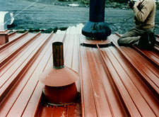
Figure 16. This plumbing vent was not centered on one of the standing seams as detailed. To avoid mistakes such as this, this type of detail should be discussed at the pre-roofing conference, as it involves coordination between the plumbing and roofing contractors. Corrective action should be taken with this type of error.
-
As with submittal approval, be cautious in approving materials, systems and details that are not in accordance with the contract documents while performing field observations (Figure 16). For example, the roofing crew may desire to use different fasteners to attach the membrane because the approved fasteners were not sent to the job site. Before accepting the fasteners, determine if wind uplift test ratings will be affected and if the membrane manufacturer will approve the alternative fasteners. Another example is a penetration detail that the foreman desires to flash differently than detailed. Is the change proposed in order to provide a better detail, or is it being proposed because it is simpler and cheaper to install? If the proposed detail is not as conservative as the original detail, it should probably not be approved. Requests to use alternate details of materials should be referred to the Designer of Record for written approval.
-
Write daily reports and give them expeditiously to the contractor (and to the roofing designer if the observer is not an employee of the structural firm that designed the roof). Report copies should be included in the file prepared for the Owner, as discussed in section 4.4.5.
Non-Destructive Evaluation (NDE)
After completion of all building construction, but before occupancy, consideration should be given to NDE of the roof to check for excessive moisture within the roof system. The purpose of the NDE is to find areas of wet insulation caused by moisture entrapment during application or leakage caused by roof system defects. Low voltage electronic leak detection may be employed continuously to monitor roofs to warn of leaks before they migrate to the building interior. This technique is usually employed on high-risk occupancies, such as hospital operating rooms, computer facilities, museums, etc. See the Integrity Testing for Roofing and Waterproofing Membranes Resource Page for further information.
At the pre-roofing conference the contractor should be notified if NDE is to be conducted. (Notification may result in greater diligence in application and care of the completed roof).
Project Close-out
At the end of the project, the owner should be provided a file with the following items:
- Contract drawings and specifications related to the roof
- Approved submittals
- Minutes from the pre-roofing conferences
- Field observation reports
- Pertinent construction correspondence related to the roof
- Warranty (if specified)
- Non-destructive evaluation of the roof.
Drawings
After the roof system is selected and the specifics of the system (such as deck type, insulation type(s) and thickness, fastener patterns, and warranty requirements) are developed, it is necessary for the roof designer to determine what details are needed and to design the details so that they are suitable for the project conditions.
Roof Plan: A roof plan should be drawn to scale and be sufficiently large to adequately convey information. It should show all penetrations and all expansion, seismic and area divider joints. The slope directions and approximate amount of slope should also be shown. The different wind uplift areas (field, perimeter and corners) should also be shown and dimensioned. References to all penetrations, roof edges and roof-to-wall details should also be indicated on the plan. (Note: For some standard details such as plumbing vents and roof drains, rather than include the detail on the drawings, referencing the manufacturer's detail in the specification is typically sufficient unless project conditions require enhancement to the standard detail). An example roof plan is shown in the Typical Roof Plan Layout detail below. If a manufacturer's standard detail is referenced, the exact detail needs to be appropriate for the condition.
Details: Details should be drawn to scale and should be sufficiently large to adequately convey the information. Illustrating details in section typically suffices. However, with complicated details, an isometric drawing may be needed.
At parapet and roof-to-wall details, the low-point of the roof should be drawn and a dashed line placed at the high point if the roof elevation varies. See Parapet Wall Schematic detail below.
After details have been drawn, it is recommended that they be reviewed by the specified manufacturer(s) prior to bidding. Care should be taken to avoid drawing manufacturer-specific details that can only be met by a single manufacturer, unless a proprietary specification is intended.
Manufacturer's Standard Details: Nearly all roof membrane manufacturers publish standard details to guide the proper installation of their products. These details should be considered as only a starting point in creating project specific details. The standard details produced by manufacturers represent the lowest acceptable level of performance. Due to competitive market pressures manufactures must keep the base price of their systems low and therefore they keep the standard details as simple as possible. The manufacturer can take an informed risk about the chances of a particular detail performing versus the cost of warranty repairs. Of course, it is the building owner who experiences the leak and suffers the bulk of the damages from this risk evaluation.
Some manufacturers publish enhanced details for high-wind warranties or for premium products. It may be advantageous to include these enhanced details into typical projects for improved performance.
It is important for design professionals to recognize which aspects of a manufacturer's details can be altered or enhanced and which aspects must be left to the manufacturer. Typically, issues such as seaming, edge attachment, base flashing and drains must comply with the manufacturer's details. On the other hand, the conditions on the standard details related to the interface with adjacent construction can be modified to include performance enhancements such as tighter air sealing, elevating base flashing on tapered edge strips, extending base flashing higher than minimums, and requiring redundant seals at penetrations.
In conclusion, do not rely exclusively on manufacturers' standard details and do not allow custom details to be substituted for standard details during construction, unless they are an improvement. The evaluation of the details requires judgment, experience, and expertise in the systems being used.
Reference Details: There are a variety of sources to draw upon for design of details. Various details for low- and steep-slope systems are included in The NRCA Roofing Manual. The NRCA details are available on a CD-ROM and should be utilized as described herein. These details can be modified with CADD or incorporated directly into contract drawings. The NRCA details are widely accepted in the roofing industry and are generally recognized as being suitable for standard conditions.
The NRCA Roofing Manual: Roofing-system-specific details are available from NRCA.
This is one of the most widely recognized technical publications in the U.S. roofing industry and provides extensive information about the design, materials and installation techniques applicable to almost all types of roof systems. It contains the following four volumes:
One volume of the manual is updated each year.
The details included in the 4 volumes of The NRCA Roofing Manual are available on CD. This CD can be used with AutoCAD® software to customize the construction details to fit your specific project needs.
Two noteworthy NRCA details are in the Chapter 10 details in The NRCA Roofing Manual: Membrane Roof Systems. They are the details for equipment support stands and the guide for clearances between pipes/walls/curbs.
1. Detail for Equipment Support Stands: This detail provides recommendations for column height as a function of the width of the equipment. By following this guidance, stand-mounted equipment will be mounted high enough to allow roof mechanics sufficient room to work underneath the stand to properly install the new roof and future reroofing.
2. Guide for Clearances Between Pipes/Walls/Curbs: This provides minimum clearances between adjacent penetrations and between penetrations and roof edges. It is recommended that the guidance should be included in the contract drawings or referenced in the specifications).
Also note that the some NRCA details show a surface mounted termination at rising walls (base flashing condition) while other details that connect the roof membrane through the wall to the weather-resistive barrier on the backup wall (through-wall flashing). The through-wall flashing-style details are generally considered more durable and should be used wherever possible.
The Sheet Metal and Air Conditioning Contractors' National Association, Inc. (SMACNA) Architectural Sheet Metal Manual also has details that are widely accepted and generally recognized as suitable for standard conditions.
AIA's structural Graphic Standards also includes a variety of low- and steep-slope details. However, unlike the NRCA and SMACNA details, the details in Architectural Graphic Standards have not undergone extensive industry review. While several of the details are suitable for standard conditions, some may be inadequate. Hence, it is recommended that the NRCA details be utilized instead.
Manufacturers of roofing products also promulgate standard details. These may also be suitable for standard conditions. Many of these details are available in CADD. However, manufacturer's details typically include propriety names for various products used in the assembly. Hence, modification of the details to delete propriety names will typically be necessary.
Modifying Reference Details: Whenever reference details are considered for inclusion in the contract drawings (or via reference in the technical specifications), the roof designer should determine whether or not the standard detail needs to be modified to account for unusual weather or building conditions. Standard details typically provide suitable performance when properly executed, provided the weather at the site and the building itself is "standard." If unusual weather conditions are expected during the life of the roof (such as very high wind loads, frequent wind-driven rain, accumulation of slush under snow), standard details may need to be modified to accommodate the non-standard conditions in which they will be required to perform in. For example, in areas where deep accumulation of slush under snow is anticipated, the height of base flashings should be increased above the typical 8" (200 mm).
Knowing when standard details are appropriate and when they are not (unless they are modified) requires judgment. To make a proper assessment of the adequacy of standard details, the roof designer needs to be keenly aware of weather and other special conditions that the roof will likely be exposed to during its expected service life. The designer also needs to possess adequate roof design knowledge in order to properly utilize adopted details, such as the NRCA details. For example: not using an independent deck-to-wall expansion joint detail when necessary can result in immediate failure of the roof base flashing system. As discussed in Section 1, if the designer's knowledge is limited, consultation with a qualified roof consultant or professional roofing contractor is recommended.
Emerging Issues
The introduction and rapid acceptance of single-ply membranes into the U.S. roofing market in the 1970s was likely the most significant roofing industry change in twentieth century. Another notable development in the 1970s was the widespread acceptance of plastic foam roof insulations, although this pales in comparison with the development of single-ply membranes. It is doubtful that another issue will be as revolutionary as the introduction of the single-plies. Since the single-ply revolution, changes in the roofing industry have been primarily driven by environmental and worker health issues and the pursuit of methods to reduce the amount of labor needed to install roof systems.
Worker Health Regulations
The most notable impact of worker health regulations on the roofing industry pertained to asbestos. Prior to 1990, asbestos fibers were used in a variety of products, including asbestos-reinforced base flashings for built-up roofs, asbestos-fibrated roof coatings and asphalt roof cements and cement-asbestos shingles. The asbestos-containing roofing materials generally offered very good performance, but due to health concerns of workers exposed to asbestos fibers during product manufacturing, product installation and roof system demolition, asbestos-containing fibers have for the most-part been phased out. In many instances, the reinforcing fibers and products that were initially introduced to replace asbestos offered very poor performance.
In the late 1990s, health concerns related to development of mold in buildings were raised. Though the water necessary to initiate mold growth can come from a variety of sources such as leaking pipes and windows, leakage from roofs is a common source of water. The mold issue has taught building owners, designers, contractors, and roofing materials manufacturers, the importance of quickly responding to leakage reports. With a quick response, the source of the leakage can be identified and corrected and steps taken to dry the building before significant mold bloom occurs.
The most notable impact of environmental regulations on the roofing industry pertained to phasing out chlorofluorocarbon (CFC) blowing agents in the 1990s. CFC was used to manufacturer extruded expanded polystyrene, polyisocyanurate, and spray foam insulation. CFC was phased out because of its role in global depletion of atmospheric ozone. As an interim measure, hydrochlorofluorocarbon (HCFC) blowing agents were used in the 1990s and early into the 2000s. HCFC had a much lower ozone depletion potential than CFC. It was not until introduction of the third generation blowing agent, hydrofluorocarbon (HFC) that a blowing agent with a zero ozone depletion rating was available. The development of the second and third generation blowing agents was technically challenging. Though the phase-ins of the new agents were generally successful, product performance problems were experienced. There are concerns about hot kettles, working with hot fluids, falls from roofs during construction, coal tar and carcinogens, and working with open flames.
Environmental Regulations
Environmental concerns have affected products containing volatile organic compounds (VOCs). With some products, the VOC (commonly referred to as "solvent") content has been reduced. In other instances, there has been a move to water-based rather than solvent-based products. It is uncertain how successful the reduced VOC products and the newer water-based products will be.
Environmental concerns resulted in the following roof design trends beginning in the mid- to late-1990s:
-
Cool Roofing and Heat Island Issues: LEED® and UFC 3-400-01, "Energy Conservation", promote the use of cool roofing, and increased energy conservation through additional insulation. Cool roof design shall follow the requirements in Chapter 1, Cool Roofs. Consider that when cool roofing is used with insulation R values greater than 24, the 'cool roof' surface has little if no influence on the energy performance of the building. Additionally, designers should be aware of the possible negative impacts of using cool roofing that may result in unintended consequences. Poor design of cool roofs in ASHRAE climate zones 4 and higher have resulted in the unintended consequence of condensation below the membrane—a result of the material's inability to warm and drive moisture downward. Roofs that experience this condensation have had to be replaced. Other unintended consequences include the overheating of masonry walls, interior spaces, roof top piping and mechanical equipment as a result of the reflected UV rays. See The NRCA Roofing Manual: Architectural Metal Flashing, Condensation and Air Leakage Control, and Reroofing. See Cool Metal Roofing.
-
High Emittance Roof Surfaces: In cooling-dominated climates, there has also been interest and regulations regarding high emittance roof surfaces.
-
Vegetative Roofs: Sometimes called "green" roofs, vegetative roofs offer several potential environmental benefits, including, reduction of the urban heat island effect (via evapotranspiration and reflectivity), oxygen generation, and reduced storm water runoff. See Vegetative Roofs.
-
Photovoltaic Collectors: However, around the early 2000s, a new generation of rooftop solar collector was introduced. Available in rack mount or PV laminate application photovoltaic systems are common today. Laminated systems are not recommended at this point due to damages and failures experienced to date. See Building Integrated Photovoltaics (BIPV).
-
Sustainable Roof Design: Highly reflective roofs, vegetative roofs and use of solar collectors can all be considered as elements of sustainable design. However, sustainable design for the building envelope considers and incorporates many other issues. See The NRCA Roofing Manual: Architectural Metal Flashing, Condensation and Air Leakage Control, and Reroofing.
-
Higher levels of insulation.
-
Greater emphasis on the importance of controlling airtightness.
Labor Reduction
Over the past several decades there have been a variety of application equipment, system designs, and product developments aimed at reducing the amount of labor to install roof systems. Trends since the 1990s include the following:
-
Wider sheets: Wider single-ply sheets for mechanically attached application are now available. Originally, sheets were approximately 5' wide. 10' wide sheets were eventually available, and then 12' wide sheets. With the wider sheets, fewer rows of membrane fasteners are required and there are fewer time-consuming field seams to fabricate.
-
Use of non-bituminous adhesives, such as foam adhesives, in lieu of mechanical fasteners to attach insulation.
-
Availability of self-adhering, single-ply membranes: Self-adhering, modified bitumen sheets were available in the 1980s, but several performance problems limited their widespread acceptance. Around the early 2000s, a variety of self-adhering single-ply membranes emerged, along with renewed interest in self-adhering, modified bitumen membranes. In addition to potentially being faster to install, the self-adhering sheets eliminate the need for adhesives and torches (and the environmental, health, and fire concerns associated with some of these other attachment methods).
-
Mechanized rooftop application equipment: Although a variety of mechanized application equipment (such as aggregate spreaders, roof cutters and tear-off machines) was in use prior to the 1990s, the weight of the equipment has increased. On larger jobs, it is not uncommon to see ATVs (four-wheelers) being used to transport materials on the roof. Larger, and thus heavier, ballast spreaders are also available. While these heavier pieces of equipment should not be detrimental to buildings with strong roof decks and deck support structures, the heavier equipment can damage older buildings with weak (or deteriorated) decks and/or deck support structures.
The Future
It is likely that as the industry moves forward, there will be important changes to products due to environmental, health, energy, or sustainability issues. The introduction of significantly different types of roofing materials is unlikely. The trend towards more sustainable roof design and construction will likely continue.
Electric leak detection will see increasing use. It is a non-destructive leak detection method recommended for all waterproofing membranes but particularly when waterproofing systems are to be covered with over burden, such as soil for vegetative roofing, pavers for a plaza, or an inverted roofing membrane assembly (IRMA). See Integrity Testing for Roofing and Waterproofing Membranes Resource Page.
The past has shown that introduction of new materials and system designs has not been easy. After a new material or system design is introduced, it has typically taken several years for unexpected problems to be identified and successfully solved. Minor changes to materials and system designs have also often resulted in problems, but these have generally been less problematic and more quickly resolved. This age-old trend is likely to be repeated in the future. It is therefore incumbent upon designers and contractors to be cautious when specifying and installing new products and system designs.
Relevant Codes and Standards
Prior to 1990, the three model building codes (BOCA National Building Code, Standard Building Code, and the Uniform Building Code) contained few provisions pertaining to roof systems. Additional provisions were added to these codes during the 1990s. The International Building Code (IBC) has many provisions related to roof systems, including reroofing projects. Code requirements pertaining to roof systems originally primarily addressed life-safety issues, such as fire resistance. However, the IBC also includes provisions pertaining to general serviceability, such as minimum roof slope.
Building code requirements can be quite different from those of the membrane manufacturer or FM Global. It is therefore important for the roof system designer to carefully consider the code requirements. The designer should determine if a building code has been adopted for the locale where the roof will be installed and, if so, what edition of the code is to be used. If the building occurs in an area that has not adopted a building code, it is prudent for the designer to voluntarily comply with the roofing-related provisions of a current edition of a model code such as the IBC.
The building code may have specific requirements regarding documentation to be provided to the building department. For example, the IBC has construction document requirements in sections 107 and 1603 (2012 edition).
Most building departments possess little expertise related to roof systems. Designers should therefore not rely upon the building department to discover non-code compliance during their plan review. Also, most building department's inspectors do not inspect the roof system. Those departments that do inspect the roof likely possess insufficient knowledge of all of the systems that they could encounter.
NRCA publishes a number of documents regarding building and energy code requirements for roof assemblies. They include:
- Guidelines for Complying With Energy Code Requirements for Roof Assemblies: International Energy Conservation Code, 2009 and 2012 Editions. This document also covers the relevant roofing-related provisions of ASHRAE 90.1—2007 and ASHRAE 90.1—2010.
- Guidelines for Complying With Building Code Requirements for Roof Assemblies: International Building Code, 2009 Edition.
- Guidelines for Complying With Building Code Requirements for Roof Assemblies: International Building Code, 2012 Edition
- NRCA Guidelines for Roof Systems With Rooftop Photovoltaic Components
NRCA also maintains a list of currently-adopted state energy codes on their website (nrca.net).
Standards
There are a large number of standards pertaining to roof systems, the majority of which were developed by ASTM. The ASTM standards typically pertain to test methods (laboratory and field) and product standards. However, there are a few design and application guides:
- ASTM D 6510 Standard Guide for Selection of Asphalt Used in Built-up Roofing Systems
- ASTM D 6369 Standard Guide for Design of Standard Flashing Details for EPDM Roof Membranes
- ASTM D 5469 Standard Guide for Application of New Spray Applied Polyurethane Foam and Coated Roof Systems
- ASTM D 5082 Standard Practice for Application of Mechanically Attached Poly(Vinyl Chloride) Sheet Roofing
- ASTM D 5036 Standard Practice for Application of Adhered Poly(Vinyl Chloride) Sheet Roofing
- ASTM D 3805 Standard Guide for Application of Aluminum-Pigmented Asphalt Roof Coatings
There are a few ANSI standards that pertain to roof systems, including:
- ANSI/SPRI RP-4 Wind Design Standard for Ballasted Single-ply Roofing Systems
- ANSI/SPRI ES-1 Wind Design Standard for Edge Systems Used with Low Slope Roofing Systems
- ANSI/SPRI FX-1 Standard Field Test Procedure for Determining The Withdrawal Resistance of Roofing Fasteners
- ANSI/SPRI RD-1 Performance Standard for Retrofit Drains
Wind Loads: ASCE/SEI 7-10 Minimum Design Loads For Buildings and Other Structures (this standard is often referred to by local code requirements and regulations)
Underwriters Laboratory (UL) and FM Global have also developed a number of standards pertaining to test methods. In addition, FM Global has several Property Loss Prevention Data Sheets (the majority pertain to wind performance). Although the Data Sheets are not "standards" because they did not go through a consensus development process, they have essentially become de facto standards:
- Standard for Tests for Uplift Resistance of Roof Assemblies: UL 580
- Standard for Uplift Tests for Roof Covering Systems: UL 1897
- American National Standard for Evaluating the Simulated Wind Uplift Resistance of Roof Assemblies Using Static Positive and/or Negative Differential Pressures: ANSI FM 4474-2004 (R2010)
Additional Resources
WBDG
Design Objectives
Functional / Operational—Ensure Appropriate Product/Systems Integration
Products and Systems
Unified Facilities Criteria (UFC) on Roofing
Unified Facilities Guide Specifications (UFGS)
See appropriate sections under applicable guide specifications: VA Guide Specifications, DRAFT Federal Guide for Green Construction Specifications, MasterSpec®
Publications and Manuals
- Flexible Membrane Roofing: A Professional's Guide to Specifications by SPRI. Published by SPRI.
- The Manual of Low-Slope Roof Systems by C.W. Griffin: This book provides information on low-slope systems, including discussion of many fundamental design issues. Published by McGraw-Hill.
- MBMA Roofing Systems Design Manual: This manual addresses metal roof systems. Published by the Metal Building Manufacturers Association.
- Modified Bitumen Design Guide for Building Owners by ARMA: This document addresses modified bitumen systems. Published by the Asphalt Roofing Manufacturers Association.
- The NRCA Roofing Manual: This very comprehensive document has information on roof decks, insulations, vapor retarders and a variety of low- and steep-slope roof coverings. The Manual is a four-volume set with one volume being updated annually. A copy of the current Manual should be in the office of every designer who designs roofs. Published by the National Roofing Contractors Association (www.nrca.net).
- The Science and Technology of Traditional and Modern Roofing Systems by H.O. Laaly: This very comprehensive book provides information on low- and steep-slope systems. Published by Laaly Scientific Publishing.
Periodicals
Websites
- Asphalt Roofing Manufacturers Association
- ASTM
- EPA Energy Star
- FM Global
- Metal Building Manufacturers Association
- Metal Construction Association
- National Roofing Contractors Association: This site includes a database of publications, including magazine articles and papers from technical conferences. Many of the listings can be downloaded.
- Oak Ridge National Laboratory
- Polyisocyanurate Insulation Manufactures Association
- RCI: This site includes a database of publications, including magazine articles and papers from technical conferences. Many of the listings can be downloaded.
- Roof Coating Manufacturers Association
- Sheet Metal and Air Conditioning Contractor's National Association
- Spray Polyurethane Foam Alliance
- SPRI
- Underwriters Laboratory Inc.
Software
- EnergyWise Roof Calculator Online: A free Web-based application that provides a graphical method of constructing roof assemblies to evaluate thermal performance and estimated energy costs under normal operating conditions.
- RoofNav: A free Web-based tool developed by FM Approvals™ that provides fast access to the most up-to-date FM Approved roofing products and assemblies.