Introduction
Within This Page
The foundation wall of a building may be a cast-in-place concrete retaining or basement wall or a structural wall complete with load-bearing pilasters. Materials used may be concrete or reinforced masonry. The foundation wall system may include an earth retention system of soldier piles and wood lagging or shotcreted rock requiring consideration of waterproofing applied to the earth retention system. For most portions of the foundation wall, water removal and control is of prime importance. However, water removal measures around foundation walls below the water table may be impractical and expensive over the long-term and the waterproofing strategy becomes critical. In the upper areas of the foundation wall thermal loading considerations must be addressed.
Readers are advised to obtain expert advice when designing systems which are below the water table or which are enclosing particularly vulnerable occupancies. Expert advice may also be necessary when dealing with field conditions.
Description
This section provides specific description of materials and systems common in foundation walls and below grade building enclosure systems in general. Descriptions and guidelines are provided on the following topics:
- Drainage Materials
- Filter Fabrics
- Damproofing
- Waterproofing Membranes
- Protection Board
- Insulation Materials
- Waterstops
- Drainage Pipe
Drainage Materials
Drainage Materials for below grade enclosures include:
- Aggregate Drainage Layers
- Prefabricated Synthetic Drainage Layers
Aggregate Drainage Layers—Aggregate drainage layers include graded pea-gravel aggregate or coarse sands. Graded pea gravel refers to naturally rounded stone between 3/16 inch and 3/8 inch in diameter. Coarse sands varying from No. 30 to No. 8 sieve are suitable. Gap-grading the sand provides uniform grain size, which accelerates drainage flow rates.
Prefabricated Synthetic Drainage Layers—These products consist of a combination of plastic composite drainage cores with adhered geotextile fabrics. The plastic composite "dimpled" drainage cores are available in various configurations and are typically constructed using polypropylene, polystyrene and polyethylene. The geotextile fabrics retain sand, soil, concrete, or grout allowing water to migrate into the free draining core. The fabrics are available in various forms including non-woven for clay type soils and woven or small opening geotextiles for sandy or high-silt type soils. Many drainage mats also include a polyethylene sheet backer to uniformly disperse the loads imposed on the membrane and reduce the potential for damage caused by non-uniform profiles (dimples) in the composite core.
Design considerations include selecting an appropriate design to achieve the required flow rate. In general, drainage core widths of 1/4 to 1/2 inch provide drainage flow rates 3 to 5 times the rate of commonly used natural backfill materials. These systems are advantageous in their lightweight design and cost effectiveness. Although marketed to be used with excavated soils during backfill in lieu of a granular drainage layer, it is recommended that a full system approach be used in applications where water leakage is not tolerable; a full system approach should include both a synthetic drainage layer and granular drainage layer.
Filter Fabrics
Geotextile filter fabrics are also used for separating differing soil types in below grade enclosure applications. This separation of differing soil types maintains flow rates of soils used as drainage layers and minimizes settlement from finer materials filling in more coarse materials. Geotextile fabrics are typically constructed using polypropylene, polyester, or nylon and are available in either woven or non-woven designs. Woven products are constructed using individual threads or filaments and have good strength and stiffness; however, the material can be penetrated by angular aggregate reducing the ability to properly filter or separate fine elements. Non-woven products are typically continuously extruded and spun and then needle-punched to create uniform openings that can be selected depending on the design. In general, when properly designed, non-woven products have good filtration and separation properties.
Damproofing
Dampproofing materials are generally applied by sprayer, roller, brush, or trowel and are often bitumen based coatings; typically applied up to 10 mils (0.25 mm) in thickness. These materials can be solvent based or water emulsions. Dampproofing is always applied on the positive side, or wet side, of the structural element.
Dampproofing is intended to control vapor diffusion through the foundation, which can contribute to damp conditions on the interior. Dampproofing is not intended to control liquid water leakage through the foundation wall; waterproofing is required to control water leakage. Since dampproofing cannot withstand hydrostatic pressures, it should not be used on structural elements below the water table where the intent is to prevent interior water leakage. Waterproofing is more effective in eliminating the risk of leakage and may be no more expensive than dampproofing, depending on the material used. Most waterproofing materials also control vapor diffusion.
Other available dampproofing technologies include both cementitious and reactive products. Cementitious products are generally portland cement based and typically trowel-applied or brush-applied. Reactive/crystalline products are typically proprietary blends made from cement, silicates, metal oxides, and chemicals introduced through concrete admixtures or surface-applied applications. These materials require the presence of moisture to set off a reaction with the concrete. Understanding the specific chemical admixture is important in determining its potential performance in below-grade dampproofing or waterproofing applications.
Waterproofing Membranes
Waterproofing membrane systems are available as either post-applied or pre-applied products for use in either positive-side, negative-side, or blind-side applications. Positive-side waterproofing systems are post-applied to the surface of the element that is directly exposed to moisture, typically the exterior side of the foundation wall. Negative-side waterproofing systems are post-applied to the surface of the element opposite the surface exposed to moisture, typically the interior of the foundation wall. Blind-side waterproofing systems are pre-applied to the area where the concrete element will be placed that is directly exposed to moisture. Positive-side systems are available in numerous materials and forms. Negative systems are generally limited to cementitious systems. Blind-side systems are typically either a waterproofing sheet or an impermeable clay-based material.
Waterproofing membranes can be categorized into four (4) types:
-
Fluid-Applied Systems—These systems include urethanes, rubbers, plastics and modified asphalts. Fluid-applied membranes are applied in liquid form and cure to form one monolithic seamless membrane. For foundation wall applications, typical cold applied fluid applied systems are approximately 60 mils in thickness. Some systems include reinforcing mesh embedded into the liquid. Hot applied, rubberized asphalt systems can be 125 mils to 180 mils thick, plus embedded 60 mil neoprene sheets.
-
Sheet-Membrane Systems—Sheet membranes used in foundation wall applications include thermoplastics, vulcanized rubbers, and rubberized asphalts. The thickness of these systems varies from 20 to 120 mils. If heat-welded seaming is employed and loose-hung membranes are tough and protected from damage by protection board, they may be effective waterproofing materials, but if a leak occurs, the leak will be difficult to locate and correct due to the loose application of the waterproofing layer in those cases. It is always better to have a continuously bonded and adhered waterproofing layer to reduce the potential for lateral moisture migration beneath the membrane.
-
Bentonite Clays—These systems include composite sodium bentonite systems with HDPE liners and geotextile fabrics, which are more common and more effective than the traditional systems. Bentonite clays act as waterproofing by swelling when exposed to moisture thus becoming impervious to water. This swelling can be 10 to 15 percent of the thickness of the base material. Bentonite is, therefore, most effective when properly confined so the product can swell to fill voids and so that it cannot be washed away. If Bentonite clay is unconfined, it can shrink upon drying, creating gaps that undermine waterproofing characteristics. Clay panels and geotextile sheets are popular for use in blind-side waterproofing applications such as on retaining earth systems and elevator and sump pits.
-
Cementitious Systems—These systems contain Portland cement and sand combined with an active waterproofing agent. These systems include metallic (metal oxide), crystalline, chemical additive, and acrylic modified systems. The latter two should not be used as waterproofing except for the most non-critical conditions. The first two systems can be applied as negative-side or positive-side waterproofing. Even these systems should only be considered for use as a secondary (back-up) waterproofing to a positive-side waterproofing system, unless they are used with special details provided by a waterproofing expert which are beyond the scope of what are usually provided by system manufacturers.
Waterproofing should be applied a minimum of 12" above finished grade, and then applied to a point 12" below the top surface of the interior slab on grade. Typically, the waterproofing is wrapped over a masonry brick shelf, or up behind the finish exterior materials at grade so that it may be terminated and shingle lapped by the weather barrier. When it is wrapped over masonry ledges, care must be taken to coordinate with masonry ties and thru-wall flashings. Where grade slopes down along an exterior wall, the waterproofing will step down incrementally so that it continues to protect the below grade, occupied space.
If the exterior wall materials will not protect the waterproofing at grade, base flashings should be used to protect the waterproofing from ultraviolet (UV) radiation exposure. These flashings are usually stainless steel to resist corrosion in contact with grade soils and moisture.
In some situations, it may not be possible to apply waterproofing directly and entirely to the foundation walls, and it may be necessary to fasten a "lens" membrane to the foundation wall to catch runoff and redirect it away from the foundation. It is recommended that a 60 mil PVC membrane or polyolefin membrane be used, set on a concave sand bed and fastened to the foundation wall with a stainless steel termination bar with standard waterproofing applied to the wall above that point. The lens membrane should slope away from the building and collect and redirect the runoff to a drain tile or sump away from the foundation
Protection Board
Protection Boards are used to shield waterproofing membranes from construction damage, damage from backfill materials in service, and ultraviolet radiation. The most commonly used protection board is a semi-flexible sheet containing an asphalt core placed between asphalt impregnated glass fiber mats. The material may have polyethylene film on one side and a glass mat surface on the other side. For some membrane applications such as hot-applied bitumen systems, the protection board is embedded into the wet membrane forming an integral part of the waterproofing membrane. Asphaltic protection boards are available in 1/16, 1/8 and 1/4 inch in thickness. Other materials sometimes used as protection layers are extruded polystyrene rigid board insulation or prefabricated synthetic drainage layers.
In general, using prefabricated composite drainage board directly against certain waterproofing membranes as a protection layer is not recommended. Although the composite board may have a polyethylene sheet on the membrane-side, this sheet is often cut, damaged, or missing. If installed, soil pressures can cause the "dimples" in the drainage core to displace or damage the waterproofing membrane. Additionally, the composite cores have sharp corners that can cut the waterproofing membrane during installation or backfill operations. Therefore, a protection layer is recommended between the waterproofing membrane and the drainage layer.
Insulation Materials
Insulation materials used in below grade enclosure applications are primarily limited to rigid extruded polystyrene board due to the need for high compressive strength and moisture absorption resistance. For optimum drainage and thermal performance, install a composite drainage board with integral filter fabric to the exterior of the insulation.
Waterstops
Waterstops should be utilized at construction joints in below grade walls, footings, slabs, and other elements where a waterproof system is required. These systems provide a secondary barrier to the passage of water across these construction joints. Waterstops are manufactured products available in a wide range of configurations and sizes. Common materials include polyvinyl chloride (PVC), neoprene, expanding sodium bentonite and thermoplastic rubber.
Although not as common, pre-installed permeable grout injection waterstop may also be considered. Typically constructed with flexible PVC, permeable grout injection tubes are installed in construction joints and are injected with grout only if leakage is observed. In some cases, the tubes may also be re-injected if leakage persists. Injection ports/sites are typically accessed from the building interior.
Common areas of concern for waterstops are at corners and laps in the materials. These details must be properly detailed and installed to be effective. In general, the manufacturer's standard details should be followed. If PVC is used, corners and laps should be heat welded and properly inspected.
Drainage Pipe
Drainage pipes, typically 4" or 6" in diameter, used in below grade systems are primarily made of corrugated PVC or polyethylene and in some cases of porous concrete. PVC and polyethylene pipes are available in smooth or corrugated configurations and are slotted on the bottom half of their cross-section to allow water infiltration. Based on some extensive excavation and waterproofing experience, it has been found that corrugated PVC drain tile piping can collapse under the weight of backfill, and the preference is to use stiffer PVC pipe if possible.
All drain tile piping should be laid onto large, river-washed aggregate stones, which is laid onto a filter fabric, which should be wrapped around and over the drain tile to try to prevent fine soils from filling the drain tile. Regarding slope to drain, drain tile is intended to be installed with some slope to ensure that the water moves toward the sump collector. The outlet must be the lowest point in the system at each juncture.
Fundamentals
Figure 2 is an overall schematic that characterizes the four functions i.e. Structural Support, Environmental Control, Finish, and Distribution as they relate to the below grade enclosure elements of foundation walls.
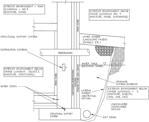
Fig. 2. Foundation Wall Schematic
The four function categories, i.e. Structural Support, Environmental Control, Finish and Distribution, are expanded below in general terms for foundation walls.
Structural Support Functions—The foundation wall system of the below grade building enclosure must be designed and constructed to support both vertical and lateral loadings.
Vertical loads exist from the dead, live and lateral loads from the structure and the wall itself. The foundation wall may be an integral part of the load bearing design of the building carrying column and floor loads from above, either as distributed loads on the wall or point loads on pilasters integral to the wall system. These walls may also be used in the lateral resisting system for the building.
Lateral loads on foundation walls exist from the soil, surcharge and hydrostatic pressure loads. Soil loadings vary with soil type and whether soil is treated as active or passive. Hydrostatic pressure loads may exist in cases of high water tables or flood events. Typical hydrostatic and soil pressures generally range from 30 to 62.4 psf per foot of depth. Surcharge loadings may include live loads from pedestrian walkways or from vehicular roadways. Areas designed as pedestrian areas should also include consideration for emergency vehicular loadings.
In many cases the foundation wall is required to resist all of these loads directly with the wall designed as a cantilever retaining wall with a large base footing or as a basement wall spanning vertically between the foundation element and supported floors. Other cases may include an earth retention system, such as piling and timber lagging, facilitating construction and designed to resist the lateral loads leaving the foundation wall to resist primarily vertical loads.
Special loadings such as blast loads are a design consideration in parking areas under and next to buildings. While the first control of these abnormal load events are through security entry control systems and restricted access, structural design considerations may also be required in the design of the foundation wall system.
Environmental Control Functions—The exterior environment that the foundation wall is subjected to includes environmental control loadings such as thermal, moisture, tree roots, insects, and soil gas. The interior environment that the foundation wall is subjected to includes environmental control loadings such as thermal and moisture. The performance of the foundation wall system depends on its ability to control, regulate and/or moderate these environmental control loadings on each side of the foundation wall to desired levels.
Likely, the most predominant environmental control loading for foundation wall systems is moisture. Moisture control is dealt with in a multiple screen/barrier type of design approach. For surface moisture loadings such as rain and snow, the first line of control is the upper screen at the exterior surface. This upper screen may consist of relatively permeable landscape areas ranging to impermeable pavers, concrete or asphalt surfaces that will shed the majority of surface moisture. The effectiveness of this initial screen in shedding moisture may influence the design of the other components of the system.
Moisture that penetrates through the upper screen needs to be directed to the exit drain located at the base of the foundation wall. This is accomplished through a drainage system at the exterior of the wall that is typically a free draining granular material. Backfilling with native, poor draining soil is not recommended as this will maintain an active water load on the foundation wall and limit its ability to control moisture ingress to the interior. As moisture moves from the upper screen through the drainage system on the exterior towards the exit drain, moisture will inevitably make its way toward the surface of the foundation wall itself. Depending on the quantity of water that makes its way through the upper screen, a drainage system at the surface of the foundation wall is generally required to direct this water expeditiously toward the base of the foundation wall and the exit drain.
In many foundation wall situations with low water table elevations, the combination of the upper screen, the exterior drainage system, the near surface drainage system and the exit drain will control the majority of the water. The key question that remains is whether to provide dampproofing or waterproofing to the surface of the foundation wall or not at all. Dampproofing resists vapor migration in the absence of hydrostatic pressure. Waterproofing resists both vapor migration and hydrostatic pressure.
Generally, waterproofing can only be eliminated in sites with exceedingly dry soil. Most building codes require dampproofing as a minimum amount of moisture protection. In these cases the remaining part of the system is a dampproofing applied directly to the exterior surface of the foundation wall. Building codes also generally require waterproofing if the ground-water level cannot be maintained at least 6 in. below the bottom of the slab-on-ground. This can be accomplished with pumping systems. In areas with greater moisture loads from hydrostatic pressure from high water tables or sensitive interior environments, a waterproofing membrane should be applied to the exterior surface of the foundation wall in lieu of dampproofing. Waterproofing membranes are predominantly applied to the positive (exterior) face of the foundation wall, however, there are negative-side waterproofing systems that can be applied to the interior of the foundation wall, and blind-side waterproofing systems that can be pre-applied to a support-of-excavation wall resulting in a waterproofing system installed on the positive side. In these cases, the concrete foundation wall is placed against the blind side waterproofing membrane.
Even when it is necessary to apply a waterproofing membrane, it is recommended to also utilize a system approach including components of exterior drainage system, near surface drainage system and exit drain. The removal of the moisture in the most complete and expeditious manner will decrease the probability for intrusion of water. However, since some municipalities charge for water pumping into storm drain systems, these costs must be weighed over the life of the structure when designing the waterproofing systems. Portions of the building permanently below the water table may require more redundant systems. For example, crystalline waterproofing is often used to provide redundancy to one of the other waterproofing systems. Some municipalities also limit pumping of groundwater as this can lower groundwater levels and affect the support of adjacent structures. When pumps are to be relied upon to discharge moisture, a backup power system should be provided in the event of power failure.
Thermal considerations are of limited concern as one gets deeper down on the foundation wall as there is a constant, thermal design condition on the exterior. As most foundation wall systems have substantial mass, e.g. concrete, insulation may only be of importance to moderate interior temperatures in the upper portions of the foundation wall where temperature conditions will fluctuate. However, the use and location of the insulation is more important on the control of moisture in terms of preventing condensation on interior wall faces for the entire height of the foundation wall. Condensation is possible in below grade conditions in warmer more humid summer conditions as below grade spaces tend to be cooler in the summer because of the insulating effect of the backfill soil. This cooling effect combined with general poor air circulation in underground spaces can result in condensation on interior wall surfaces.
The higher soil temperatures on the exterior also create the need to provide at least a damproofing on the exterior of the foundation wall to resist the strong interior vapor drive. In fact, in some situations, conditioned below grade spaces are subjected to a constant inward vapor drive during summer as the interior space is air conditioned, and in the winter the interior space is heated resulting in a lower vapor pressure than the exterior condition as the soil stays relatively constant in terms of vapor pressure.
Finish Functions—Two areas of finishes are of importance in relation to foundation walls. The first area is the finishes of the interior space. This finish is dependent on the interior use whether it be a controlled office environment or a non-controlled parking environment. Typical finish systems may include paints, stucco, or framed walls with drywall. In many applications the interior finish is simply the interior surface of the material used for the foundation wall, i.e. concrete or concrete masonry units.
The second area is the finish to the exterior near grade level. Proper treatment of this area is critical in terms not only of aesthetics but also durability.
Dampproofing/Waterproofing in all situations should be carried up above the upper screen and integrally tied into the building façade flashing and waterproofing. Many waterproofing membranes need to be shielded from ultraviolet radiation to prevent deterioration and as such some type of exterior finish is required. In many cases the exterior façade element, whether it be brick, stone, etc., is carried down to just below grade level to properly transition and protect this sensitive area.
Distribution Functions—Foundation walls may contain distribution systems such as electrical and electronic runs. At times these systems are run internally in the interior surface finish system or in ceiling space. Distribution systems within the foundation walls themselves must be treated with careful consideration, as they can also be conduits transporting air and moisture within the structure.
Applications
Upper Screen Design Considerations for Surface Runoff
Many areas around a building's perimeter at grade are subjected to high amounts of surface runoff from the high use of fenestration and impermeable wall façade materials, such as thin stone and EIFS. The first and most effective defense against this water is to slope the upper screen surface away from the building a minimum of 5% near the building edge. Proper design to connect downspouts into perimeter drain systems directly instead of flowing onto the area directly adjacent to the foundation wall is prudent in design.
Important design considerations include sloping the surface away from the structure, providing a suitable drainage system from the upper screen through the granular backfill, and a synthetic drainage layer that extends down to the perimeter drain.
Exit Drain Design Considerations
Drainage pipe at the perimeter of the foundation wall should be surrounded by a free draining granular material that is wrapped in filter fabric to prevent fines from filling in the porous spaces of the granular material. Drainage pipe should have a slope of at least 0.5%, but preferably 1.0%.
Damproofing/Waterproofing Membrane Selection
The designer must consider the overall water management system relative to site conditions and loadings to determine if dampproofing or waterproofing is required. If in doubt, it is clearly prudent to err on the conservative side and provide a waterproof system.
For waterproof systems the first consideration is whether to use positive or negative side waterproofing. Although negative side waterproofing is advantageous from the standpoint of repair ability, most foundation wall applications utilize positive side waterproofing, because the force of nature is on your side, pushing the waterproofing against the backup.
Depending on site conditions and depth of the foundation wall, positive side waterproofing can either be installed from the exterior or directly to the lagging in a blind-side application prior to placing concrete. For application from the exterior, the next design decision is to use fluid applied or sheet products. Sheet products are advantageous in terms of consistency in product material properties and thickness, but the primary drawback is the numerous laps that are required. Laps should be installed so that the upper sheet is lapped over the lower sheet so that water is shed naturally across the lap. Where sheet materials are utilized, it is preferred to adhere the membrane fully and continuously to the substrate to prevent lateral migration of leaks, and to heat-weld or positively bond the seam laps.
With fluid membrane systems, proper application in terms of coverage and thickness is critical to performance, and this should be monitored throughout the installation. The key advantage to fluid systems is their monolithic nature and self-flashing abilities as the material is applied in liquid form. One potential disadvantage is the inability of some liquid products to span cracks or opening of construction joints, which may occur on new buildings soon after application.
In blind-side (positive-side, without access due to tight lot lines, under slabs on grade, or other reason) waterproofing assemblies, products may include sheet materials of thermofusible HDPE or PVC, bentonite, or other similar proprietary sheet products. In all applications, protection of the membrane and proper lapping and sealing of joints is critical. Methods for concrete placement include cast-in-place between the lagging and interior forms, or spray applied shotcrete. With bentonite systems, lapping of bentonite sheets is typically backlapped from the exterior if concrete placement involves pouring from the top of the wall. Bentonite sheets are also typically shingle lapped with the lateral direction of the concrete placement. When using cast-in place concrete, detailing of the form ties is critical and using single sided forms braced back to the slab can minimize this detailing. Detailing around shoring piles and soil tie-back anchors can be challenging and reducing the number or frequency of these types of penetrations will increase the potential for good performance of the waterproofing system. Diligent inspection and repair of the waterproofing after reinforcing steel is placed is a critical step, as steel placement often results in damage to the waterproofing that can not be repaired once concrete is placed. Shotcreting can result in undesirable conditions such as voids behind reinforcing steel, and as a result some waterproofing manufacturers do not recommend their products for this application. In combination with bentonite sheet waterproofing, these voids can be detrimental, since the bentonite can swell into the voids and loose its waterproofing integrity. Careful attention to installation is critical during both cast-in-place and shotcrete applications in blind-side waterproofing assemblies.
Membrane Protection
The best design intentions in selecting and detailing waterproofing systems can be undermined through damage from construction. For positive side applications, the installation of protection boards or insulation layers as quickly as possible after membrane installation is critical to prevent mechanical damage form subsequent layers and backfill and form ultraviolet radiation. Prefabricated synthetic drainage layers are sometimes used in lieu of protection board for protecting waterproofing membranes. Caution is advised with use over softer liquid applied materials as the drainage layer may dig into and breach the membrane. With these softer waterproofing membranes protection board is recommended under the synthetic drainage layer or drainage layers with integral polyethylene backing may also be appropriate.
When designing the thermal, protection, and drainage elements to the exterior of below grade foundation walls, a slip plane should be introduced vertically within the assembly. Location of the slip plane may vary depending on the design; however, it should be included in all assemblies. The slip plane can reduce stresses imposed on the membrane during controlled backfill operations; these stresses can cause membrane damage, wrinkling, loss of adhesion, or delamination. Extruded polystyrene insulation boards should be properly supported on the footing to prevent vertical movement. In addition, mechanical attachment of insulation or other materials that would penetrate or place stress on the membrane should be avoided. If adhesives are used to attach an element to the membrane, the adhesive pattern should be installed in small dabs to allow vertical water discharge and reduce the potential for hydrostatic pressures imposed on the waterproofing membrane.
The slip plane is between the XPS and the drainage board. The drainage board should have the protection sheet on the backside of the core to promote better movement against the insulation.
Building Façade Termination
Of critical importance in any building is the proper detailing and integration of the vertical building facade system and the below grade building system. The integration of the two systems requires careful consideration to insure that all moisture, air and thermal criteria for each system are satisfied at the transition interface. There is a combination of environmental design loadings at this interface such as surface water, runoff, and cavity wall drainage.
Façade terminations often produce the accumulation of moisture at or near the grade line of the building with the surrounding area. A special flashing behind face stones of buildings or special flashing and treatment of the exterior slab edge where it is adjacent to ground features is required.
Special treatment is also needed at all door entries. Common practice for wall terminations or door entries is to provide slope away from the building as previously indicated. Limiting the direct contact of moisture with the isolation or flashing detail at the envelope seal is a very effective practice.
Penetrations
Condition appraisals and trouble shooting of below-grade structures reveals common sources of leakage that occur at penetrations. Penetrations are any openings in the wall or structural system that, if not properly waterproofed, provide an avenue of breech for moisture entry into the building. Sewer pipe penetrations, water line entry penetrations, drain basins in the floor slab or sleeves for electrical, gas or communication are all common penetrations, typically with their own design or detailed features. These features, however, leave much to be desired with respect to sealing and waterproofing. Penetrations can also become quite exotic such as steam penetrations or other features that require special treatment. Because of the unique nature of penetrations and Special Features, no single rule or criteria can govern or apply to the effective treatment thereof. However, classification of common penetration types and features helps to ensure effective treatment and proper function.
Isolation, insulation and waterproofing of certain piping that undergoes large temperature changes are often underestimated for resulting movement. Where expansion and contraction of the services or pipes entering the building occurs, a sleeve through the wall that is discontinuous with the penetration piping is required. Sealing these generally requires application of elastomeric boots that seal to the housing and to the exterior pipe. Other surfaces such as gas pipes, signal or electrical should generally be done with due consideration for the nature of the sleeve through the exterior wall and the depth below grade of the penetration.
Common knowledge suggests that the seals serve as a back-up function and that avoiding moisture build-up is the principle objective for obtaining a leak free building at penetrations. Notre that leakage may occur at a penetration and flow behind the waterproofing if a lateral path exists.
Wall Expansion Joints
Wall expansion joints should be designed to accommodate the anticipated structural movement. Consult with a structural engineer regarding possible movement. For treatment of leaks providing amplified external drainage media similar to that required on the exterior wall is highly effective. Special emphasis is placed on evacuating the water at the wall base to avoid water build-up in the back fill or drainage system.
Wall/Floor Construction Joints
Construction joints have been effectively treated in most applications by a waterstop manufacturer's recommended details. For many membrane types, a multiple layer detailing of the membrane, proper isolation and allowance for joint detailing is generally effective for construction joints. A liquid membrane cant covered with an elastomeric flashing extending to the edge of the footer and several inches above the cant has proven historically effective. Where the foundation wall is required to be waterproofed, adding a waterstop to the construction joint is recommended. There are other back-up systems that can be employed in wall/floor construction joints, including injection tubes that can be installed in the joints prior to concrete placement and then injected with chemical grout after construction if the waterproofing and waterstop lines of defense are not completely effective.
Details
The following details can be downloaded in DWG format or viewed online in DWF™ (Design Web Format™) or Adobe Acrobat PDF by clicking on the appropriate format to the right of the drawing title.
The details associated with this section of the BEDG on the WBDG were developed by committee and are intended solely as a means to illustrate general design and construction concepts only. Appropriate use and application of the concepts illustrated in these details will vary based on performance considerations and environmental conditions unique to each project and, therefore, do not represent the final opinion or recommendation of the author of each section or the committee members responsible for the development of the WBDG.
The details, graphics, and related information shown in the details are intended to illustrate basic design concepts and principles only and should be considered collectively with the appropriate narrative sections of the Whole Building design Guide (WBDG). The information contained therein is not intended for actual construction, and is subject to revision based on changes and or refinements in local, state, and national building codes, emerging building envelope technologies, and advancements in the research and understanding of building enclosure failure mechanisms. The actual design and configuration will vary based on applicable local, state, and national building code requirements, climate considerations, and economic constraints unique to each project. Full compliance with manufacturers' recommendations and recognized industry standards is recommended, and should be reflected in the appropriate sections of the project specifications.
Foundation Wall—Typical System (Detail 1.2.1) DWG | DWF | PDF
Foundation Wall System—Blind-Side Waterproofing (Detail 1.2.2) DWG | DWF | PDF
Foundation Wall—Fluid-Applied Membrane System (Detail 1.2.3) DWG | DWF | PDF
Foundation Wall—Sheet Membrane System (Detail 1.2.4) DWG | DWF | PDF
Foundation Wall—Pipe Penetration Detail Without Sleeve (Detail 1.2.5) DWG | DWF | PDF
Foundation Wall—Pipe Penetration Detail With Sleeve (Detail 1.2.6) DWG | DWF | PDF
Foundation Wall—Façade Transition to Masonry Veneer (Detail 1.2.7) DWG | DWF | PDF
Emerging Issues
For emerging issues refer to General Overview section.
Relevant Codes and Standards
For codes/standards refer to General Overview section.
Additional Resources
WBDG
Products and Systems
See appropriate sections under applicable guide specifications: Unified Facility Guide Specifications (UFGS), VA Guide Specifications, Federal Guide for Green Construction Specifications, MasterSpec®
Publications
For resources including texts, guides, and web pages refer to General Overview section.
NOTE: Photographs, figures, and drawings were provided by the original author unless otherwise noted.