by Joseph C. Dean, P.E. and Steve Geusic, P.E., for the Director, Corrosion Policy & Oversight (DCPO), (DASD) [Materiel Readiness]
Updated: 04-22-2022
Introduction
Within This Page
The waterfront with its support structures serves as the land-based transition point for seagoing vessels while they are in port. Once they are connected to power, water, waste collection and other utilities support, the waterfront becomes an extension to the existing land-based installation. Coastal structures include aids to navigation, piers, wharves, dry docks, fleet moorings, seawalls, groins, jetties, and breakwaters that are all designed to ensure safe and efficient operation at the land ocean interface. Bulkheads, pilings, structural framing, decks, utility trenches, dolphins, compressed air, electric (power), steam, water, waste, and fuel lines and fender systems are additional facilities associated with waterfront and coastal structures. Each of these facilities are subject to corrosion. A thorough understanding of the corrosion stresses on waterfront and coastal structures is vitally important to ensure continued and responsive mission support, safety, readiness and prevention of environmental contamination.
DESCRIPTION
This Knowledge Area includes corrosion prevention and control (CPC) insights and information for Waterfront and Coastal Structures and the associated facility categories. This Knowledge Area has been developed to help the facilities professional better understand the corrosion challenges that exist in the waterfront environment. Typical waterfront and coastal facilities and structures include (See Figure 1):
- Piers
- Wharves
- Pier decking
- Dockside Supporting Utilities
- Lay down areas adjacent to piers and wharves
- Cathodic Protection Systems
- Dolphins
- Piles and Pile Caps
- Sheet piling
- Drydock
- Floating Berths
- Breakwater
- Shore protection
- Tie backs and Fender Systems
- Mooring systems
- Boat lifts and hoists
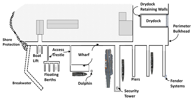
Figure 1: Typical Waterfront Structures
Source: Steve Geusic, P.E.
These structures can be buried or submerged and subjected to heavy vertical and lateral forces in addition to chemical deterioration of corrosive forces. Awareness of the corrosion risks for waterfront and coastal facilities and structures such as piers and wharves requires the interaction of many engineering disciplines such as structural, electrical, environmental, mechanical, civil, and specialty engineering areas such as cathodic protection and paints and coatings. Each discipline has an essential role to play in ensuring that the waterfront infrastructure is designed, constructed, and sustained in the best possible life cycle cost effective manner.
These facilities are almost always operationally focused and mission impacting when readiness levels are not up to required levels. Corrosion impacts these facilities as follows (see the Facilities Corrosion Impacts on Operations and Missions Table ):
-
Corrosion Deterioration Description: For the Department of Defense (DoD), there is a direct interface between the waterfront facilities and Naval Fleet operations. Corrosion can adversely affect Fleet readiness. Waterfront zone exposure causes high structural and system corrosion deterioration resulting in reduced support capabilities. Sea level rise (fixed elevation exposure to high salinity impacts from gradual and dramatic variations in sea level) has exacerbated the risk levels. Wood destroying organisms such as marine borers, insects, and fungi can cause significant damage and deterioration of marine timber structures. Corrosion can have a significant effect on operational systems which are then more prone to failure leading to structural collapse and leakage of hazardous or flammable materials. Corrosion often occurs before it is noticed (see Table 1 for Common Depictions of Corrosion). Conducting an effective Sustainment, Restoration and Modernization (SRM) program preceded by good design and quality construction are essential for continuous system responsiveness; a facilities management life cycle sustainment process helps in the early discovery and resolution of corroded Coastal and Waterfront Structures.
-
Factors Contributing to Corrosion: Salt water is an excellent electrolyte contributing to an aggressive corrosive environment. Hydrostatic forces, wind, salt spray, currents, tides, waves, and ice all contribute to corrosion and erosion of waterfront systems and structures. Waterfront operations and industrial activities (pollution, fuels, hazardous materials, deicing salts, and stray currents) often add to the corrosion severity. Humidity, rain, chloride containing environments, salinity from deicing salts (especially salt water, dramatic shifts in tides), structural loading, applied chemicals, erosive factors, temperature, moisture, and water borne pollutants impact waterfront systems. Utilities are particularly susceptible to corrosive forces. Failures are often not visible until the facility is in extremis.
-
Operations and Mission Impacts: Corrosion negatively impacts facility availability and increases structural degradation, accompanied by high sustainment costs, and reduced life cycle. Corrosion of waterfront systems result in reduced capacity and berthing availability. Repairs are costly since access to structures can be difficult (immersed, buried, or foundational). Loss of berthing or the associated utilities can be a huge concern, especially if the ship is preparing to deploy. Environmental contamination from leaking fuel and hazardous material poses a significant environmental concern causing fleet operation reduction and work arounds. The cost to handle fuel and hazardous materials that leak from corroded facilities usually exceeds the costs associated with the control of the corrosion responsible for the leak. In some cases, the products of corrosion themselves are hazardous and corrosion must be controlled to prevent direct environmental damage.
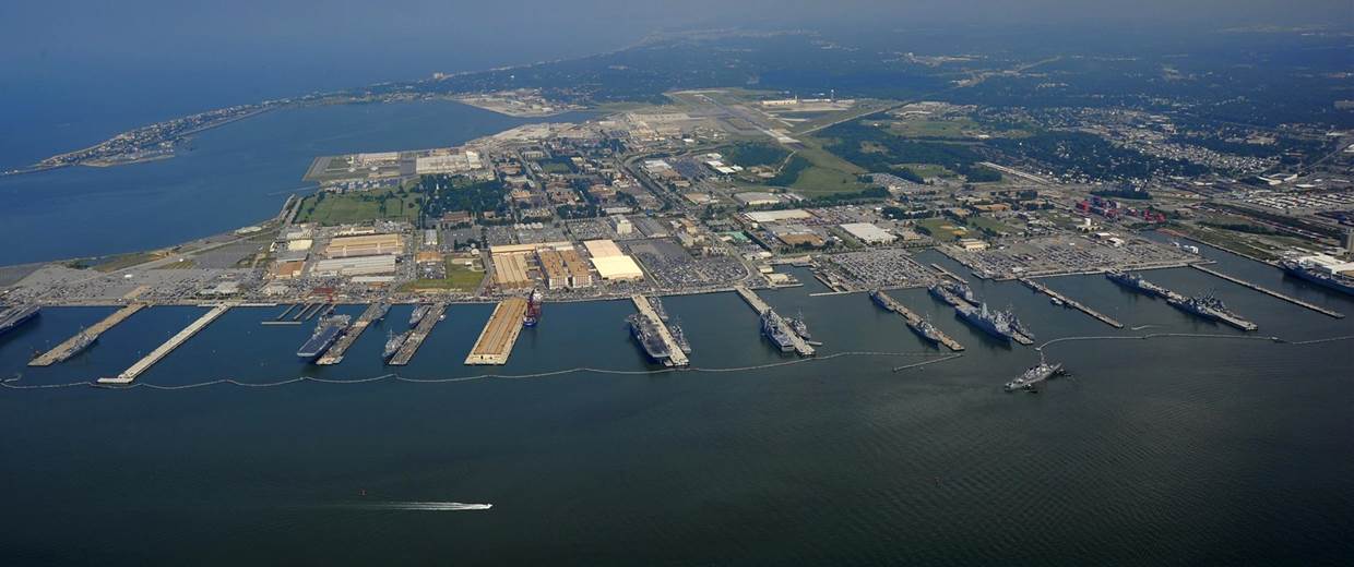
Photo 1: The Water Front Operation
Source: MC 1st Class Christopher B. Stoltz / U.S. Navy via Reuters file
The Waterfront Environment
The waterfront environment is often the most severe atmospheric corrosion zone. Individual components may have corrosive forces from multiple electrolyte mediums in addition to the atmosphere such as seawater, soil, and concrete. Understanding the waterfront environment and its risks and stresses on facilities is an absolute must for the supporting engineering disciplines. Salt water is an excellent electrolyte contributing to an aggressive corrosive environment. Hydrostatic forces, wind, salt spray, currents, tides, waves, and ice all contribute to corrosion and erosion of waterfront systems and structures. Structures are often buried or submerged and subject to heavy vertical and lateral forces in addition to corrosion caused by chemical deterioration. Waterfront operations and industrial activities (pollution, fuels, hazardous materials, deicing salts, and stray currents) often add to the corrosion severity. Wood destroying organisms such as marine borers, insects, and fungi can cause significant damage and deterioration of marine timber structures. Environmental Severity Classification (ESC) for the waterfront area is typically C5 (Very High Corrosivity), and must be addressed during the planning, design, material selection, and construction processes. Photo 1 and Figure 2 provide insights into the complexity and dynamics of the waterfront environment.
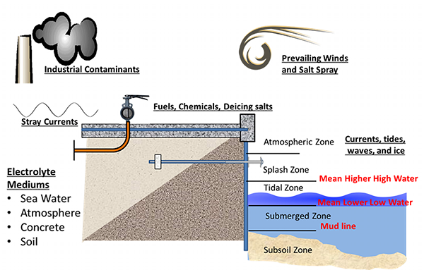
Figure 2: The Waterfront Environment
Source: Steve Geusic, P.E.
Waterfront Zones
The waterfront is composed of five zones (see Figure 2): The atmospheric zone, the splash zone, the tidal zone, the submerged zone, and the subsoil. The zones are delineated by the mean lower low water datum and the mean higher high-water datum:
-
The MEAN LOWER LOW WATER (MLLW) datum is the average of the lower low water height of each tidal day observed over the National Tidal Datum Epoch. The National Tidal Datum Epoch is a specific 19–year period adopted by the National Ocean Service as the official time segment over which tide observations are taken and reduced to obtain mean values
- The MEAN HIGHER HIGH WATER (MHHW) datum is the average of the higher high-water height of each tidal day observed over the National Tidal Datum Epoch
The type of CPC implemented for components or portions of a structure is influenced by the zone in which it resides:
-
The Atmospheric Zone is any portion of the waterfront structure above the splash zone.
- The Splash Zone is the portion of the structure just above the tidal zone. This portion of the structure is predominantly dry but is likely to intermittently wet by wave action and wind driven spray. See Figure 2 for a depiction of the Coastal Zone and Transitions. In UFGS 03 31 29 Marine Concrete with Service Life Modeling the splash zone is defined as:
- 2 meters above the tidal zone for locations protected by seawalls or sheltered from open ocean waves
- 6 meters above the tidal zone for unprotected locations
-
The Tidal Zone is defined as the portion of the structure that is located between Mean Lower Low Water (MLLW) and Mean Higher High Water (MHHW); In areas with minimal tides, this would be defined as the area located between Mean Sea Level (MSL) and Mean High Water (MHW).
-
The Submerged Zone is the submerged portion of the structure that is located below Mean Lower Low Water (MLLW). In areas with minimal tides, it would be defined as that portion of the element below Mean Sea Level (MSL).
Understanding the interaction between each zone such as differential aeration cells, will often dictate the appropriate use of coatings, encasement, and cathodic protection strategies.
Corrosion Types
Table 1 shows 10 different types of corrosion, all of which are fully explained in the Corrosion Science Knowledge Area. CPC management solutions for waterfront and coastal structures depend upon understanding these corrosion types and selecting the appropriate corrective action.
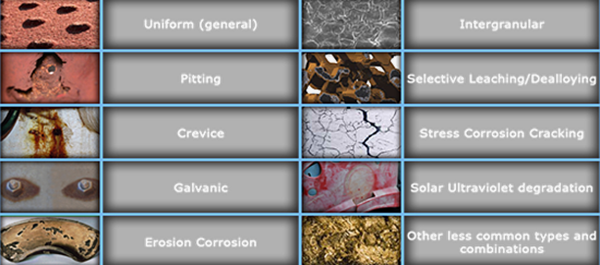
Table 1: Common Depictions of Corrosion
Photo Credit: D, CPO
Steel Corrosion in Seawater
Interaction of the various waterfront zones and associated forces leads to a complex distribution of corrosion on steel structures. The corrosion versus depth profile in the submerged area is due to a differential aeration cell. The high availability of oxygen at the tidal area makes this zone cathodic with respect to the zone just beneath the mean lower low water level where the corrosion is high. A similar but less dramatic effect also occurs at the mud line. To protect steel in waterfront structures, protective coatings are critical. Coatings or encasement is necessary to prevent corrosion in the atmospheric zone, splash zone, and the tidal zone. The coating in the tidal zone will reduce the attack just below mean lower low water. Cathodic protection can effectively prevent corrosion in the submerged zone and is particularly effective when used with a factory applied coating on pilings. It is usually more cost effective to cathodically protect an existing bare steel structure in the continually immersed zone than to attempt to coat the structure using expensive underwater coatings. See Photo 2 which shows extensive corrosion and failure of a steel sheet pile bulkhead without protective coatings or cathodic protection.
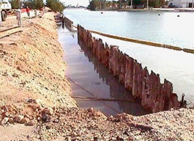
Photo 2: Badly corroded steel sheet pile bulkhead with areas of complete failure. No corrosion control applied.
Source: Waterfront and Coastal Structures Training Course, Steve Geusic, P.E.
Soil and Seawater as an Electrolyte
Seawater and other natural waters, such as brackish and river waters, is saturated with dissolved oxygen creating a biofilm promoting the cathodic corrosion reaction. Because of the presence of a large amount of dissolved salts (sodium chloride (NaCl)) that are ionized, this makes seawater an excellent conductor. The chloride ion is particularly aggressive as it causes a breakdown of passivity.
Since Soil is an electrolyte medium, waterfront structures buried in soil like sheet pile and metal pipelines suffer from corrosion. Soil resistivity, moisture content, pH values, and the presence of chlorides, sulphides, and bacteria, are the key factors in its corrosivity on buried metals. Another key factor is the difference in soil composition along the structure. Hydraulic fill is soil often used behind waterfront structures such as bulkheads. It is typically drawn up by the suction head of a dredge, pumped with water through a pipe, and deposited in an area being filled or reclaimed. Hydraulic fill may be of good quality, consisting of granular materials, or may consist of plastic organic silt, which is considered poor quality. Utility piping and tie rods may pass through different adjacent soil compositions like hydraulic fill and select backfill at waterfront structures such as bulkheads, caissons, and piers.
Generally, soil resistivity has the greatest impact on corrosion with respect to soil properties and environmental conditions. Soils with the poorest drainage (clays) and highest moisture content are generally the most corrosive and lower resistivity values. Conversely well drained soils (sands and gravels) have higher resistivity and are considered the least corrosive. Backfilling pipe trenches and excavations with sand or gravel improves the long-term protection in corrosive poorly draining soils. Acidic soils with pH of 0 to 4.5, may represent a serious risk to common construction materials and metal. Soil in contact with waterfront structures are often contaminated with chlorides as a result of wave action, overtopping and hydraulic gradients. As a result, chloride ions are harmful, as they participate directly in pitting initiation of metals and their presence tends to decrease the soil resistivity.
Waterfront structures buried in soil like sheet piles and metal pipelines suffer from corrosion because of one or more of the following soil conditions:
- Low Resistivity values
- High moisture content
- Low pH values (Acidity)
- Presence of chlorides, sulphides, and bacteria
- Differences in soil composition like hydraulic fill
The corrosion potential can be increased due to:
- Dissimilar materials, including new and old adjacent materials
- Surface scratches and irregularities
- Presence of stray currents
Waterfront and Coastal Zone Protection Techniques
Methods of Corrosion Control in the Waterfront and Coastal Zone include:
- Altering the Environment
- Good Design Practices with design geometrics considerations
- Corrosion Allowance
- Material Selection
- Protective Coatings
- Cathodic Protection
Altering the Environment
Examples of Altering the Environment include:
- Using a selective backfill around a buried structure
- Using corrosion inhibitors such as fuel additives
- Modifying the structure to provide adequate drainage
- Relocating sources of stray currents
- Reducing wave action and erosion with the addition of breakwaters, groins, jetties, rip rap, and stone revetments
Altering the environment is best employed during design, however, careful identification and characterization of corrosion problems will often reveal opportunities for changing the environment to control corrosion even after the structure is built.
Good Design Practices
Practicing and employing good design and construction practices is a professional responsibility. Here are a few for your consideration:
- Avoid details that can trap water or create crevices
- Structures should be designed so that water is not trapped since water greatly accelerates deterioration
- Many coatings are designed for atmospheric exposure and not immersion
- Avoid relying on drain holes as they often become plugged and provide challenges for uniform covering of protective coatings
- Poor welding details often cause crevices and are oxygen-deficient areas that accelerate metal corrosion
- Continuous welds should be used rather than skip welds
- A painter must be able to apply a uniformly thick, continuous film to obtain protection of a surface
- Sharp edges should be rounded because a uniformly thick coating cannot be applied over the edge due to wet coatings will draw thin on them
- Sharp interior corners should be avoided since they may receive an excessive coating thickness
- Irregular surfaces such as welds and other projections should be ground smooth to eliminate projections through the paint film
- Weld-spatter, which is loosely bonded to the steel, must be removed as it creates areas for crevice corrosion and as the mill scale becomes dis-bonded, the barrier film will be broken
Corrosion Allowance
In a marine environment, designing in corrosion allowance is not sufficient without other forms of protection such as protective coatings and cathodic protection. This is due to the various types of corrosion present. The use of thicker materials for corrosion allowance is only effective where low-rate uniform corrosion is anticipated. In soils, typically, greater sacrificial thicknesses are required when soil salinity levels (chlorides) exceed 2000 ppm and soil resistivity is less than 2000 ohm–cm. For timber fender piles, dolphin piles, and other timber piling requiring lateral load-carrying capacity and impact, consideration should be given to increasing pile diameter because preservative pressure treatment tends to reduce lateral load-carrying capacity.
Material Selection
General material selection considerations include:
- Determine the severity of the environment and exposure
- Identify probable types of corrosion (see Table 1)
- Select more corrosion resistant materials
- Avoid dissimilar metal usage
- Avoid incompatible environments and materials (for example, aluminum should not come into direct contact with concrete, because the alkalinity of the concrete will attack the aluminum)
When selecting the type and grade of the material, it is critical to identify the severity of the environment and probable types of corrosion that may affect the component. Inspect the component detail and surrounding assembly of components. Determine the electrolyte and amount of exposure. Look for water traps, crevices, welding, and dissimilar materials. Note that there is a wide range of materials in use on the waterfront (steel, weathering steel, nonferrous metals, concrete, timber, fiber reinforced plastics (FRP), ultra-high molecular weight (UHMW) plastics, and high-density polyethylene (HDPE), composite piles, each with its unique challenges, protection, CP, coating, and deterioration profiles.
Protective Coatings
Consider coating mechanisms for protection which may include the following:
- Barrier Protection—Protective coatings and linings attempt to isolate the structure from the environment (electrolyte)
- Cathodic Protection (CP)—Some protective coatings have a high loading of fine zinc particles. Once cured, the electrical contact between the particles and underlying steel provides a type of CP
- Inhibitive Pigments—Some pigments are added to primers to inhibit corrosion at the coating/metal interface
Note: UFC 3-190-06 Protective Coatings and Paints and various Unified Facility Guide Specifications (UFGS) provide detailed information on coating requirements and guidance for various components and systems:
- Most coatings provide corrosion protection by forming a barrier that is relatively impermeable to moisture and electrolytes
- Keys to a successful coating involve selection of the right coating for the substrate and the environment, good surface preparation, and proper application.
- Surface preparation is recognized as being one of the most important factors in coating performance and is about 45% of the total painting costs. Keys to successful surface preparation include removing contaminants that inhibit adhesion, providing a surface profile for tight bonding, and ensuring sharp edges and projections are ground smooth, weld spatter removed and crevices filled.
- Grease and oil will prevent tight bonding of coatings, as will loose dirt, dust, rust, scale, and chalk from old paint. Salt remaining on metal surfaces after cleaning may accelerate osmotic blistering. Salt can become trapped in metal pits and crevices where it is difficult to remove.
- Mill scale is a bluish, somewhat shiny oxide residue that forms on steel surfaces during hot rolling. Although initially rather tightly adhering, it soon cracks, pops, and dis-bonds. Unless completely removed before painting, mill scale will later cause the coating to crack and expose the underlying steel.
- While smooth surfaces may prevent a tight bonding of coatings, too great a surface profile may present coating difficulties for relatively thin primers. Pinpoint rusting occurs soon when peaks of blasted metal profiles receive only thin films of coating.
- Selecting the appropriate application method involves evaluating the desired appearance, ease and cost of the method, specialized equipment and the operator skill, access to the substrate, and environmental requirements (see Figure 3).
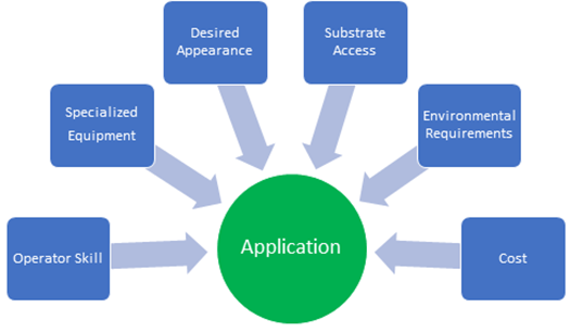
Figure 3: Application Considerations
Source: Steve Geusic, P.E.
For example, trying to coat an existing structure in the continually immersed zone requires dewatering or using expensive underwater coatings. Because of the difficulties in accessing the substrate and the cost of the coating, it is usually more cost effective to cathodically protect an existing bare steel structure in the continually immersed zone than to attempt to coat the structure. All coatings degrade with time. However, premature failure of the surface coat or more severe cracking and peeling which exposes the substrate must be prepared to prevent corrosion.
For limited or localized damage, spot cleaning and repair may be suitable. Spot repairs require cleaning of exposed metal and surrounding tightly adhering topcoat(s). The coating edges at damaged areas should be "feathered" (beveled) to achieve good adhesion of the patch and provide an attractive finish. Primer and topcoats used in these repairs should completely cover the metal and overlap onto the existing coating system to prevent weak joints of new to old coating.
There is extensive guidance and advice for coating steel, weathering steel, and nonferrous metals. Refer to the appropriate criteria. This includes UFC 4-151-10 General Criteria for Waterfront Construction, UFC 4-152-01 Design: Piers and Wharves, and UFGS 09 97 13.26 Coating of Steel Waterfront Structures, Zero Voc, (SZC) Splash Zone Coating)
Cathodic Protection
Properly installed and maintained CP systems can reduce life cycle costs by extending a utility's lifecycle. These systems can also reduce the potential liability from premature failure of utilities, such as gas line explosions and jet fuel leaks, while also ensuring the avoidance costs associated with the leaks such as fines, environmental cleanup, remediation and disposal of contaminated soil, and monitoring requirements (see Photo 3 and Figure 4).
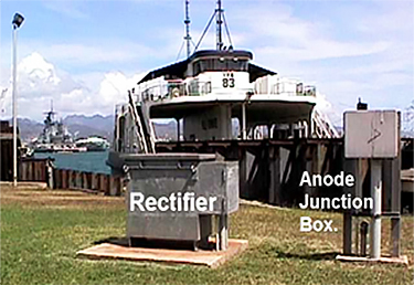
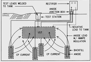
Photo 3: Cathodic Protection System (Waterfront Course WBDG)
Source: Steve Geusic, P.E.
Figure 4: Impressed Current Cathodic Protection System for Underground Storage Tank
Source: Steve Geusic, P.E.
In marine environments, a Cathodic Protection System can greatly extend the life of the submerged zones of steel waterfront structures. For buried and submerged structures, a Cathodic Protection System in conjunction with other protective measures such as material thickness incrementation, protective coatings and encasement is recommended for:
- Steel sheet piling bulkheads
- Steel Bearing piles for piers
- Steel fender piles for piers
- Mooring components
Provide CPS and protective coatings for the following buried or submerged metallic utility systems regardless of soil or water corrosivity:
- Petroleum, Oil and Lubricant (POL) pipelines
- Oxygen pipelines
- Underground POL and gasoline storage tanks
- Underground hazardous substance storage tanks
- All water storage tanks interiors
- Other buried or submerged new steel, ductile iron, or cast iron utility pipelines not mentioned above when the soil resistivity is below 30,000 ohms
Note that POL piping systems require special consideration for protective coatings as well as cathodic protection systems. Aboveground and immersed fuel lines can be coated much the same as steel fuel tanks with a multiple coat epoxy system. New coating as specified in "UFGS 09 97 13.26 Coating of Steel Waterfront Structures, Zero Voc, (SZC) Splash Zone Coating" is applicable. A petrolatum paste/tape system has also been used very effectively in protecting fuel lines under piers. See the Petroleum, Oil, and Lubricants (POL) Storage and Distribution Systems Knowledge Area for additional insights.
Cathodic Protection is often used on steel sheet pile bulkheads in the submerged zones in addition to protective coatings and concrete caps to a depth of 3 ft. below Mean Low Water. Other marine structures utilizing cathodic protection include mooring components, ship and boat hulls, and floating pontoons.
A cathodic protection system can be rendered fully or partially inoperative due to a lack of maintenance and repair which is all too common. Regularly scheduled maintenance inspections are recommended to minimize risk of failure of the cathodic protection system. Coatings and CP should most always be used in conjunction with each other for buried or submerged structures. Both are required by law for Underground Storage Tanks (UST) and certain Petroleum, Oil and Lubricant (POL) lines.
Designers need to employ a CP subject matter expert and ensure that all the parameters are considered when designing, installing, and maintaining a CP system in the waterfront zone. For additional information on CP see DoD Continuing Education Courses (login account required), CPC Source Training Page, and Cathodic Protection Knowledge Area. See also CP assessment, design, installation and sustainment (see UFC 3-570-01 Cathodic Protection and UFC 3-570-06 Operation And Maintenance: Cathodic Protection Systems).
Waterfront Dockside Utilities Considerations
Corrosion prevention and control requirements for utilities in the waterfront area is required and covered in UFC 4-150-02 Dockside Utilities for Ship Service, UFC 4-150-07 Maintenance and Operation: Maintenance of Waterfront Facilities, UFC 3-570-01 Cathodic Protection, and UFC 3-570-06 Operation and Maintenance: Cathodic Protection Systems and UFC 4-151-10 General Criteria for Waterfront Construction. Corrosion resistant material selection impacts distribution lines, supports, covers, access panels along with how each line connection is made which also include the appropriate grounding techniques. Attention to these details will ensure that the required utility services will be available on demand throughout the anticipated life cycle. See Figure 5 for an example of waterfront utility distribution line details.
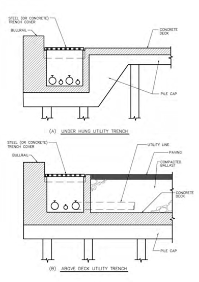
Figure 5: Example Elevation Details—Waterfront Distribution Lines
Source: UFC 4-150-02 Dockside Utilities for Ships Service
Dockside utilities systems support might include:
- Permanent salt or non-potable water
- Steam and condensate
- Potable water
- Compressed air
- Sewage
- Ship oily waste generation
- Electrical
- POL
- Hazardous waste collection
At a minimum, hangers, bolts and specially fabricated supports and braces must be hot dip galvanized after fabrication. Where salt spray exposure is severe options include:
- Application of epoxy coatings
- Stainless steel
- Fiberglass support systems
- Special alloy bolts, such as Monel bolting
For steam and condensate piping under a pier, wharf, or in a drydock where submergence may occur:
- Encase in a pressure-testable, prefabricated conduit system
- Use a corrosion-resistant conduit coating
- Use a Polyethylene heat-shrinkable sleeves and/or high temperature tape wrapping at joints and fittings
Utility mains and laterals serving utility connections must be protected from damage by waves, wind, floating debris or ice, tidal immersion, and corrosive exposure to saltwater and spray. It is preferable to place them in the utility corridor of a double deck pier or in trenches or tunnels of a single deck pier. Exposed above-deck mounting of utility services is discouraged. Although the trench covers need not be watertight, use a good seal at joints to prevent accidental seepage of spilled liquids. Frequently spaced drains should be placed along the trench to prevent flooding.
MDACS
The Marianas Navy and Marine Corps Design and Construction Standards (MDACS), lists corrosion related guidance for corrosion in general and specifically for utility systems and exterior structures. Guam's hot humid climate requires special design, knowledge, material selection, mechanical design and construction methods to prevent corrosion problems, structural failure, and moisture problems. Absent careful attention to these details, costly repairs and loss of use critical facilities will occur while repairs and mitigation actions are being performed.
The following guidance highlights are required in Guam where the ESC Zones are 4 and 5. Designers, engineers and sustainers can gain understanding of what is required under those conditions and apply them to local situations where similar ESC Zones exist. MDACS guidance for Guam construction and sustainment includes:
- Material selection is key to success in hot humid design
- All surfaces of materials shall be sloped and drained to prevent standing water
- Isolate dissimilar materials to prevent galvanic action
- Reinforced concrete is the structural material to be used unless otherwise indicated. Provides guidance on the use of ASTM A 706 and A615 steel
- Exterior metal framing, fasteners, and connections shall use properly selected stainless steel (or equal) corrosion protection
- Provide protective coatings and cathodic protection for buried metallic fuel or hazardous waste storage tanks and associated pipelines
- All steel water structures shall have a protective coating system, which prevents the current from flowing between the metal and electrolyte, and an impressed-current cathodic protection system
- The Public Works Utilities Criteria requires:
- Under pier pipe hangers and other structural support provisions, including hanger rods and nuts/bolts, shall be 316 stainless steel.
- Dockside Ship Wastewater Provisions: Pipe hanger assemblies for suspended under pier collection manifold piping shall be 316 stainless steel (threaded rods, pipe saddles, nuts & bolts); provide locking nuts on assemblies.
- New waterlines under piers shall have an epoxy-polyamide coating system conforming to MIL-P-24441.
Relevant Criteria Highlights
The following is a representative list of some specific applicable UFC and UFGS and their highlights. For a more complete list of resources see the "Relevant Codes, Standards, and Guidelines" Section at the end of this page.
-
UFC 1-200-01 DoD Building Code provides very specific guidance for design, construction and sustainment actions related to CPC, especially in corrosion-prone locations. See below quoted content:
- Note that "any project site within 1 mile of seawater is ESC C5. Any project site within 1 to 6 miles of seawater is ESC C4, unless the installation ESC as stated in Appendix A is higher." See additional guidance concerning calculated values.
- "Considerations include life-cycle maintenance costs and potential for corrosive microenvironments."
- The UFC identifies the waterfront and coastal locations as a corrosion prone location and requires the following:
- "For structures proximate or at the waterfront, in addition to atmospheric corrosion, design for the presence of hydrostatic forces, wind, salt spray, currents, tides, waves, ice, marine borers, insects, and pollution from waterfront operations. Some common grades of stainless alloy such as Type 304 or 316 are susceptible to corrosion when immersed in salt or brackish water."
- "For corrosion prone locations, provide added corrosion protection to the design such as, but limited to, the flowing:
- Where material options are provided in a UFGS, use the most durable options.
- Provide higher level of corrosion protection as defined in the appropriate corresponding UFGS.
- Do not use unprotected ferrous metal unless there are no alternatives.
- Coat galvanized steel with an industrial coating.
- Use Type 316L. \1\ 304L, 304, or 316 /1/ stainless steel or duplex stainless steels where stainless steels are used.
- Coat aluminum with an industrial protective coating or heavy-duty anodized coating.
- Isolate dissimilar metals (for example, aluminum and steel, stainless steel and carbon steel, and zinc-coated steel and uncoated steel) by appropriate means to avoid the creation of galvanic cells which occur when dissimilar metals come in contact."
- "Detail designs to prevent accelerated deterioration of facility components. Design geometries that prevent collection of debris, allow water to readily drain in all situations, incorporate sealed joints between components, are protected from mechanical coating damage, and avoid dissimilar materials in direct contact with each other. Follow best engineering and design practices to prevent galvanic. Corrosion. Slope surfaces and pavements to drain away from the structure. Avoid designs that tend to direct corrosion elements to any specific area od a structure. Minimize the flow of water, airborne contaminants (for example, salt and pollutants), and humid air over susceptible materials when designing facility components, systems, and assemblies."
- "Tidal and splash zones will experience higher corrosion than continuously immersed or atmospherically exposed zones."
- "For submerged or partially submerged structures, account for differences in corrosion potential associated with each zone (for example, atmospheric. Splash, tidal, submerged, and subsoil)."
- See Appendix ESC for DoD Locations, identifies the ESC Zone for each of the DoD installations around the world, which then drives the selection of the types of materials and processes that should be used for corrosion-prone locations.
-
UFC 1-300-02 Unified Facilities Guide Specifications (UFGS) Format Standard Defines standards for the use of UFGS. Requires "when the selection of a material, component, or system for corrosion prevention, life cycle cost effectiveness, or durability depends on the location, application, conditions, or atmospheric and chemical environment. In the notes, provide direction on identifying and selecting those variables. Use International Organization for Standardization (ISO) 9223 and Environmental Severity Classification (ESC) factors, to help specify when to use materials, coatings, and other design elements in each project location or atmospheric environment. Additionally, provide direction on what item to use based on other relative criteria such as soil corrosivity, ultraviolet exposure, solar radiation, biological, or other factors causing deterioration of a material or its properties because of a reaction of that material with its chemical environment. Additionally, provide direction on what item to use based on other relative criteria such as soil corrosivity, ultraviolet exposure, solar radiation, biological, or other factors causing deterioration of a material or its properties because of a reaction of the material with its chemical environment."
-
UFC 3-190-06 Protective Coatings and Paints provides requirements and technical guidance for the effective use of paint-type coatings to protect common materials such as metal, concrete, pavements, gypsum board and wooden structures at military activities from deterioration. Requires paints and coatings that are durable and minimize the need for preventative and corrective maintenance over the expected service life of the component or system. Defines coating systems for specific uses. Requires coating systems specifically designed for waterfront structures (also section above discussing protective coatings for additional information).
-
UFC 3-570-01 Cathodic Protection delineates the use of "CP systems in conjunction with other protective measures such as proper material selection, protective coatings, and encasement, for the following submerged metallic waterfront structural systems:
◦ Steel sheet pile bulkheads along waterfront or waterway
◦ Steel bearing piles for piers and wharves
◦ Steel fender piles for piers and wharves
◦ Submerged mooring components br>
◦ New waterfront structures, as well as POL, utilities, fire protection, etc.- Petroleum, oil and lubricant (POL) systems, waterfront structures, and utility systems have been found to be the most critical facilities in terms of a combination of risk from corrosion, the need for continuous direct support of base operations, and the life cycle cost effectiveness of utilizing appropriate corrosion control systems." (Note that utility and POL systems are found in the waterfront zone.)
- Evaluate the economic feasibility of providing CP systems for existing steel waterfront structures and reinforcing steel in concrete.
- Addresses pre-engineered CP for pier pilings.
- Requires evaluation for the use of CP on existing waterfront structures.
- The UFC provides extensive information and guidance on specific systems, locations and related information.
-
UFC 3-570-06 Operation and Maintenance: Cathodic Protection Systems provides guidance for operation and maintenance of CP systems including the elements of a good CP program. "CP is considered an integral part of the design, construction, operations and maintenance of facilities" [under the cognizance of NAVFAC EXWC]. "Waterfront structures, POL systems, and utility systems have been found to be the most critical facilities in terms of a combination of risk from corrosion, the need to provide a continuity of direct fleet support, and the cost of effectiveness of utilizing appropriate corrosion control systems." It should be used by field personnel to perform scheduled inspections and preventive maintenance and to troubleshoot and repair CP systems. Information on non-routine field measurements is also included to enable technical assistance personnel to troubleshoot problems beyond the normal capability of field personnel to isolate or correct. Delineates mandatory CP systems use.
-
UFC 4-150-02 Dockside Utilities for Ship Service provides guidance for dockside utilities. Discusses CP and Corrosion protection in marine environments. A few of the corrosion related instructions are:
- Where salt-spray exposure is severe, add corrosion protection for hangars and support assemblies.
- Splash and atmospheric zones will require reapplication of coatings and encasements for maximum system service life.
- A qualified corrosion engineer must be provided for CP Systems. The UFC is very specific about qualifications of engineers and corrosion specialists engaged in the design, construction, and operation of these systems. [See the UFC for specific wording and requirements]
- Provides extensive guidance on the construction, access and covers of utility trenches. Utility mains and laterals serving utility connections must be protected from damage by waves, wind, floating debris or ice, tidal immersion, and corrosive exposure to saltwater and spray. It is preferable to place them in the utility corridor of a double deck pier or in trenches or tunnels of a single deck pier. Exposed above-deck mounting of utility services is discouraged.
- Provide CP System and protective coatings for:
- Petroleum, Oils and Lubricants (POL) pipelines
- Oxygen pipelines
- Underground POL and gasoline storage tanks
- Underground hazardous substance storage tanks
- Water storage tanks
- Other systems as defined
- Delineates specific requirements, concerns and materials selection and use where salt or brackish waters are present for equipment and materials.
- Addresses location of collecting sewers, pump stations and utility trenches for increased functionality and reduced corrosion.
-
UFC 4-150-07 Maintenance and Operation: Maintenance of Waterfront Facilities contains many references to corrosion and the appropriate mitigating actions.
- Describes materials in use on the waterfront and approaches to inspection, repair, rehabilitation, and maintenance. A thorough inspection program that includes identification of corrosion-related issues is essential to maintaining and sustaining waterfront facilities.
- Provides extensive descriptions of corrosion damage, inspection tables (see the Figures for waterline steel structures checklists), guidance for inspection of materials and facilities (e.g., quay walls) and the associated inspection report format.
- Addresses corrosion in supporting structures such as foam-filled fenders.
- In addition to inspections, the UFC provides insights into repairing corrosion damage and recommended materials for use in the waterfront zone. For example, it recommends specific procedures for installing cathodic protection systems to protect steel sheet piles.
- This is an excellent document for design engineers for waterfront structures. Through understanding the corrosion risks and associated deterioration processes, designers will be able to mitigate potential corrosion damage, thereby extending facilities' service life.
-
UFC 4-151-10 General Criteria for Waterfront Construction requires the following:
- Weathering steel to be coated in the splash zone and other areas not boldly exposed to sun, wind, and rain. There are no consistent data on the rate of corrosion loss for steel surfaces in contact with various soils, so that consideration should be given to coating these surfaces in the same manner and degree as for ASTM A36/A36M, Carbon Structural Steel.
- In tropical environments, and other locations where corrosion is particularly severe, encase steel pilings in concrete jackets to at least 0.61 m (3 ft) below MLLW and provide cathodic protection for the submerged and buried sections of steel. Encase steel H-piling in concrete in and above the tidal range and to a minimum depth of 1.5 m (5 ft) below MLW. Cap steel sheet piling with concrete rather than with a steel channel or timber. Partial concrete encasement of steel piles creates a zone of high potential at the concrete encasement-to-bare steel pile interface where submerged. Provide CPS in these circumstances in addition to the partial encasement.
- Bituminous or plastic coatings are not considered effective below the mudline and require special care to avoid damage during driving. Except for temporary structures, give substructure timbers a preservative treatment. Use a species that will accept deep treatment such as Southern pine or Douglas fir. Do not use untreated timber for permanent structures. Resistance to borers and decay of any untreated lumber - even of species presumed to be of superior resistance - is still inadequate for long-term use. Encase species that do not accept preservative treatment.
- When rehabilitating existing steel pile bulkheads by driving new sheets outboard:
- Electrically isolate new piling from old piling
- Electrically isolate new tie rods from existing sheet piling by cutting a hole in the old piling and providing a di-electric sleeve through the pile.
- Coat tie rods and new piling on all sides.
- Provide Cathodic Protection System
- Utility mains and laterals serving utility connections must be protected from damage by waves, wind, floating debris or ice, tidal immersion, and corrosive exposure to saltwater and spray. It is preferable to place them in the utility corridor of a double deck pier or in trenches or tunnels of a single deck pier. Exposed above-deck mounting of utility services is discouraged
- Although the trench covers need not be watertight, use a good seal at joints to prevent accidental seepage of spilled liquids. Frequently spaced drains should be placed along the trench to prevent flooding.
- Discusses factors affecting loss of steel due to corrosion (location, exposure to salt spray, tidal planes, stary electric currents, etc.).
-
UFC 4-152-01 Design: Piers and Wharves provides extensive discussion of material strengths and weaknesses and requirements. Corrosion issues are detailed. A few highlights include:
- For deck-supported structures and for support of piping and conduits, aluminum members are useful. However, do not use unprotected aluminum underwater or in the splash zone. To prevent corrosion, aluminum should be electrically isolated from adjacent materials by nonconductive gaskets, washers, or bolt sleeves. In certain applications nonferrous metals are more resistant to corrosion by seawater and marine atmosphere than steel.
- Concrete enhanced with fly ash has proven to be the best material for pier and wharf construction, and, when properly designed and constructed are highly durable in the marine environment.
- Corrosion of prestressed concrete pile reinforcement can be controlled with "proper mix design and, extreme cases, by epoxy coating reinforcement."
- Aluminum members are useful for deck-supported structures and for piping and conduit support. That said, aluminum should be electrically isolated from adjacent materials.
- Fiberglass-reinforced plastics (FRP), ultra-high molecular weight (UHMW) plastics, and high-density polyethylene (HDPE) are being increasingly used in waterfront construction.
- Disadvantages of composite materials which include low strength, uV light deterioration, long term durability and high cost are addressed. In non-shaded applications ensure the resins are formulated to enhance UV resistance and specify ASTM D4329 Standard Practice for Fluorescent Ultraviolet (UV) Lamp Apparatus Exposure of Plastics to specify UV performance.
-
UFGS 03 31 29 Marine Concrete With Service Life Modeling This is a complex UFGS that provides very specific guidance covering the requirements for reinforced concrete exposed to marine and chloride environments for projects with a defined service life. In addition, this guide specification should be used for projects with concrete exposed to weather in locations with Environmental Severity Classifications (ESC) of C4 and C5 and where deicing salts are used on the structure, where service life modeling is appropriate. It contains specific requirements for quality control (actions taken by the Contractor) and quality assurance (actions that may be taken by the Government). This guide specification includes provisions for performing concrete service life modeling.
-
UFGS 09 90 00 Paints and Coatings addresses "requirements for painting of new and existing, interior and exterior substrates." Discusses corrosion and invokes UFC 1-200-01. Delineates ESC requirements for ESC Zones C3, C4 and C5 and ASHRAE 90.1 humid locations in climate zones A, 1A, 2A, 3A, 4C and 5C. It includes contractor qualification requirements (SSPC QP 1, QP 2, etc.) and refers to SSPC, NACE, and MPI Standards. Topics include coatings, corrosion, rust, deterioration, mold, and mildew.
-
UFGS 09 97 13.26 Coating of Steel Waterfront Structures, Zero VOC, (SZC) Splash Zone Coating addresses requirements for coating new or existing steel-sheet piling and other steel waterfront structures may also be used for repairing and coating aged surfaces.
- A coating condition survey (CCS) is required for maintenance coating designs.
- Addresses qualifications and certifications requirements for the third-party protective-coating specialist, the coating-inspection company, coating contractors, testing laboratory, individuals applying coatings, and other relevant parties.
- Provides extensive requirements on the coating system, execution, including surface preparation and application, inspection and quality control.
- Note that the complexity of the application of these coatings and the associated process is consistent with the dynamics of the waterfront zone and the life cycle requirements for the facility.
-
UFGS 31 62 13.20 Precast/Prestressed Concrete Piles states, "Cement type and quantity of cement required in mix design is dependent upon the environment, soil conditions, need for corrosion protection, and location of piling" and in the Reinforcing Steel section, "Minimum cover for reinforcing steel in concrete structures is dependent upon the environment, soil conditions, need for corrosion protection, and location of piling." Similar wording can be found in UFGS 31 62 13.24 Concrete Cylinder Piles.
-
UFGS 31 62 16.16 Steel H-Piles addresses CPC in the marine environment. CPC for steel H-piles includes splash zones, seawater protection, the use of coating systems, cathodic protection and steel encasement or metal jacketing.
While the UFC and UFGS highlights list above is not all-inclusive, it does contain insights into the magnitude of design, construction and maintenance of waterfront and coastal structures, especially in corrosion-prone locations. Considering and addressing these issues will assist in achieving CPC such that the design supports the mission and meets life-cycle expectations. It will also ensure that all design choices are made to account for the realities of waterfront dynamics. Environments are evolving, with more intense storms, temperature changes, and higher sea levels. Therefore, decisions on structure placements, the extent of splash-zone coverage, orientation of facilities, and material selection will have a direct impact on the extent of corrosion and CPC measures required to keep facilities operationally ready.
It is recommended that the designer carefully review each criteria document to ensure that the appropriate materials are selected and placed in service along with the associated processes. Submittals may include shop drawings, product data, samples, test reports, certificates, manufacturer's instructions, and operation and maintenance data. Understanding Corrosion Science (see Corrosion Science Knowledge Area) as it affects Waterfront and Coastal Structures will help the designer and Sustainment, Restoration and Modernization (SRM) manager make decisions that create facilities that are life cycle cost effective and more durable.
Waterfront and Coastal Structures Sustainment, Restoration, and Modernization (SRM) Insights
Figures 6 and 7 provide insights into sustainment management program flowcharts and considerations. The use of BUILDER™ Sustainment Management System (SMS) provides for the creation of a database, assessment and maintenance management of facilities assets.
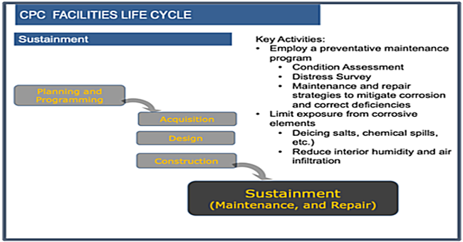
Figure 6: CPC Facilities Life Cycle (Design Service Life)
Source: Steve Geusic, P.E.
Figure 7 illustrates the sustainment maintenance process and the associated workflow. Identifying and tracking building system deficiencies through this process will ensure that the necessary work will be scheduled and accomplished in a timely process.
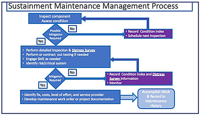
Figure 7: Sustainment Maintenance Management Process
Source: Steve Geusic, P.E.
The broad area of Waterfront and Coastal Structures presents a long list of challenges for the facilities manager. This diverse range of facilities must be represented accurately in any SMS and along with the associated inspections, preventative maintenance, and SRM actions to keep them operational. The alternative to having a good, responsive sustainment program for waterfront and coastal structures is "break down maintenance" which is never good and always drives last minute decisions and actions. This usually results in costly repairs, rather than ensuring that system sustainment decisions and repairs are accomplished in a more cost-effective manner over time.
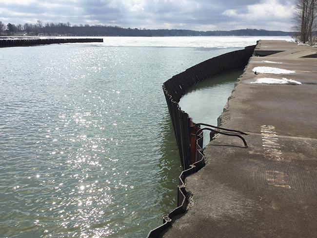
Photo 4: Buffalo District leadership assessment of Fair Haven pier
Source: Photo by Shaina Souder, U.S. Army Corps of Engineers, Buffalo District
For waterfront areas, repairs may be beyond local funding and project authorities which means that planning and avoiding "breakdown maintenance and repair" is an absolute must. This may involve underwater inspection techniques as well as specialized repair teams for submerged structures. The following information highlights the types of repairs that exist in the waterfront and coastal zone. The information is not complete, but it can give the reader some ideas about types of work that could be required. Refer to the relevant UFC and UFGS for complete requirements. See UFC 4-150-07 Maintenance And Operation: Maintenance of Waterfront Facilities for complete information and guidance.
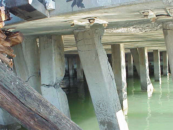
Photo 5: Pier Damage
Source: U.S. Coast Guard District 11
Reinforced Concrete repairs are one of the leading maintenance costs associated with U.S. Navy piers and waterfront structures. The service life of concrete repairs using conventional repair methods is often observed to only be approximately 7 years. The conventional repair method includes:
- Removing spalled/chloride contaminated concrete
- Using squared saw cuts to remove concrete
- Don't feather patch edges
- Replace corroded rebar as necessary
- Providing appropriate concrete mix design
To extend reinforced concrete repair service life:
- Use form and pressure pump concrete procedures
- Use of cathodic protection in selected areas may be economical
Note that enhanced repair methods utilizing better substrate surface preparation, embedded galvanic anodes, and form and pressure pump concrete placement is expected to double the service life of the concrete repairs to 14 years.
Typical repairs for steel piles and sheet piles include:
- Coatings
- Concrete encasement
- Installing a concrete cap or face
- Patching
- Partial and full replacement
- Cathodic protection
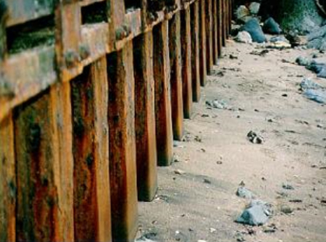
Photo 6: Steel Sheet Pile Bulkhead Coating Deterioration
Source: Steve Geusic, P.E. Waterfront and Coastal Structures Course (wbdg.org)
The steel sheet pile bulkhead pictures in Photo 6 had the protective coating scoured away by wave action within eight years. As a result, the area above the sand is well corroded where the area below the mud-line is cathodically protected and is near the original design thickness. Concrete encasement is the recommended repair.
When rehabilitating existing steel pile bulkheads by driving new sheets outboard:
- Electrically isolate new piling from old piling
- Electrically isolate new tie rods from existing sheet piling by cutting a hole in the old piling and providing a dielectric sleeve through the pile.
- Coat tie rods and new piling on all sides.
- Provide Cathodic Protection System
Timber structure rehabilitation and repair include:
- Concrete encasement and caps
- Plastic and polyvinyl pile wraps
- Applying underwater curing epoxy and fiber reinforced wrap
- Replacing timber pile with new timber or concrete pile
- Repair of dolphins
- Repairing/replacing timber components (superstructure, chocks, wales, and fender piles)
- Reinforcing or installing a tie-back system
These are just a few of the challenges and possible fixes for some of the waterfront facility structures. SRM program supported with accurate data, thorough planned inspections and recurring maintenance, and. a responsive public works force will make a huge difference in keeping facilities operational. Being prepared for (and expecting) damaged facilities should be part of every SRM program.
For more insights into CPC sustainment management see the CPC in Operations and Maintenance (O&M), and, Sustainment, Restoration, and Modernization (SRM) resource page. Additional information is provided on SMS, Builder™, and CPC data collection.
Summary
The Waterfront Zone has a myriad of facilities and structures that must be maintained and ready to have a successful transition from ship (or seagoing vessel) to shore. This includes the complex support and logistics chain. This zone is dynamic and highly susceptible to corrosion damage and interruptions. Facilities professionals who plan, design, and construct these facilities are challenged by the forces of nature and the everchanging parameters that exist in this Zone. It is an absolute imperative that these professionals understand everything that there is to know about the risks, materials, requirements, and sea-shore transitions (utilities, mooring, piers, wharves, etc.). The SRM professionals are challenged because sustaining these facilities comes with a huge price tag. The pressure is on the Facility Managers to ensure that the facilities in the waterfront zone are mission ready for the operating fleet and others who support the fleet. Responsiveness to any issue must be immediate to reduce the existing hazards and to improve fleet readiness.
The Waterfront and Coastal Structures Knowledge Area summarizes some of those risks and requirements as well as highlighting the UFC and UFGS criteria that must be considered when doing any kind of work on waterfront and coastal structures. There is so much more to know on these topics, but the knowledge provided on this page represents a good place to start with references to research to do the best possible job for the operating and supporting forces.
ADDITIONAL RESOURCES
Department of Defense
Unified Facilities Criteria (UFC)
- UFC 1-200-01 DoD Building Code
- UFC 1-300-02 UFGS Format Standard
- UFC 3-190-06 Protective Coatings and Paints
- UFC 3-220-01 Geotechnical Engineering
- UFC 3-250-01 Pavement Design for Roads and Parking Areas
- UFC 3-270-01 O&M Manual: Asphalt and Concrete Pavement Maintenance and Repair
- UFC 3-270-08 Pavement Maintenance Management
- UFC 3-570-01 Cathodic Protection
- UFC 3-570-06 Operation and Maintenance: Cathodic Protection Systems
- UFC 4-150-02 Dockside Utilities for Ship Service
- UFC 4-150-06 Military Harbors and Coastal Facilities
- UFC 4-150-07 Maintenance And Operation: Maintenance of Waterfront Facilities
- UFC 4-151-10 General Criteria for Waterfront Construction
- UFC 4-152-01 Design: Piers and Wharves
- UFC 4-159-03 Design: Moorings
Unified Facilities Guide Specifications (UFGS)
- UFGS 03 31 29 Marine Concrete With Service Life Modeling
- UFGS 03 31 30 Marine Concrete
- UFGS 09 90 00 Paints and Coatings
- UFGS 09 96 00 High-Performance Coatings
- UFGS 09 97 13.26 Coating of Steel Waterfront Structures, Zero Voc, Splash Zone Coating
- UFGS 26 42 13 Galvanic (Sacrificial) Anode Cathodic Protection (GACP) System
- UFGS 26 42 15 Cathodic Protection System for the Interior of Steel Water Tanks
- UFGS 26 42 17 Impressed Current Cathodic Protection (ICCP) System
- UFGS 26 42 19.10 Cathodic Protection Systems (Impressed Current) For Lock Miter Gates
- UFGS 31 62 16.16 Steel H-Piles
- UFGS 31 62 19 Timber Piles
- UFGS 31 62 19.13 Timber Marine Piles
- UFGS 31 62 13.20 Precast/Prestressed Concrete Piles
- UFGS 31 62 13.24 Concrete Cylinder Piles
- UFGS 35 59 13.14 20 Polymeric Piles
Whole Building Design Guide
- Corrosion Prevention and Control Source
- Corrosion Toolbox
- CPC Source—Environmental Severity Classification (ESC)
- Corrosion Prevention and Control Checklists Tool
- CPC Source—Training
- Cathodic Protection
- Corrosion Science
- Piers and Wharves
U.S. Army Corps of Engineers - Public Works Technical Bulletin (PWTB)
- PWTB 420-49-29 Operation and Maintenance of Cathodic Protection Systems
- PWTB No. 420-49-37 Cathodic Protection Anode Selection
Association for Materials Protection and Performance (AMPP) [National Association of Corrosion Engineers (NACE) and Society for Protective Coatings (SSPC)]
- SP0169 Control of External Corrosion on Underground or Submerged Metallic Piping Systems
- SP0285 Corrosion Control of Underground Storage Tank Systems by Cathodic Protection
- SP0388 Impressed Current Cathodic Protection of Internal Submerged Surfaces of Carbon Steel Water Storage Tanks
- SP0193 External Cathodic Protection of On-Grade Carbon Steel Storage Tank Bottoms
- SP0196 Galvanic Anode Cathodic Protection of Internal Submerged Surfaces of Steel Water Storage Tanks
National Electrical Manufacturers Association (NEMA)
- ANSI/NEMA C57.12.29 2006 Electrical Standards and Product Guide
- ASTM A242/A242M Standard Specification for High-Strength Low-Alloy Structural Steel
- ASTM A588/A588M Standard Specification for High-Strength Low-Alloy Structural Steel, up to 50ksi [345 MPa] Minimum Yield Point, with Atmospheric Corrosion Resistance
- ASTM A606/A606M Standard Specification for Steel, Sheet and Strip, High-Strength, Low-Alloy, Hot-Rolled and Cold-Rolled, with Improved Atmospheric Corrosion Resistance
- ASTM A690/A690M Standard Specification for High-Strength Low-Alloy Nickel, Copper, Phosphorus Steel H-Piles and Sheet Piling with Atmospheric Corrosion Resistance for Use in Marine Environments
- ASTM A709/A709M Standard Specification for Structural Steel for Bridges
Organizations
- American Society of Civil Engineers (ASCE)
- FHWA Resource Center—Pavement and Materials Team
- AMPP Training and Certification
- STI (Steel Tank Institute) Training and Certification