Introduction
Within This Page
Buildings frequently have plaza decks below grade. The planning, development, detailing and construction of waterproofing for such features are significant. Although much more complex and far more maintenance intensive, these features are generally not treated with the same detailing attention that roof assemblies receive. Protection, drainage and isolation along with thermal considerations must be incorporated into the design. Requirements for overhead waterproofing in tunnels or building obtrusions are significant and need to be treated accordingly. Design of plaza deck surfaces, green-scape and tree or soil planter features above buried elements requires special design consideration.
Plaza decks are subject to some of the most accelerated and vigorous deterioration and distress of any structural system. Harsh exposure conditions from exposure, moisture, thermal effects, weathering, and traffic often reduce these systems serviceability at a rate even surpassing that of parking and bridge deck slabs. Accordingly, special analysis of plaza decks aesthetic, wearing, moisture protection and isolation, and structural support systems, should be performed.
Plaza deck systems generally disintegrate and become unserviceable for three reasons:
- Ineffective design
- Poor construction
- Abnormal "unexpected" loadings.
Other common causes of plaza deck deterioration or failure are: severe exposure (including freeze thaw), chemical applications, overload, and/or improper materials selection and application.
Each of the above categories (listed features) is capable of working independently or in concert with other elements to cause premature plaza deck surface or waterproofing distress (service impairment) or subsequent damage over years of use exposure and traffic.
Description
This section provides specific description of materials and systems common in plaza decks.
A plaza deck system is any supported slab that provides green-scape, tree planters, and/or vehicle and pedestrian movement over occupied space. Unlike the roof of a building, which is only exposed to weathering and the elements, plaza decks have numerous special features supplemental to their common waterproofing characteristic. Depending on the type of structure the vehicular use may be limited to cleaning equipment or light vehicles. Under special circumstances plaza decks may be required to support truck and bus traffic or even construction equipment. A unique defining characteristic is the waterproofing requirement over occupied space, which at some level in the plaza deck system, interfaces with the wearing surface and/or green-scape or tree-planters to produce high potential for distress, membrane leaking, and/or plaza deck surfacing degradation.
Figure 4 illustrates the basic components of a plaza deck system.
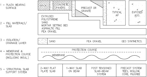
Fig. 4. Plaza Deck System Schematic
Overburden
Consideration should be given to the selection of the overburden and the components above a waterproofing membrane. Protection board, insulation drainage layers and overburden are installed on top of a waterproofing membrane. The selection of the overburden is a significant part of an overall waterproofing system. For concrete overburden, steel rebars, wire mesh, etc. should not come in direct contact with a waterproofing membrane as damage to the membrane can occur during placement and screeding operations. The overburden should not be above the top edge of waterproofing flashing terminations. The components above a waterproofing membrane should all be compatible and be compatible with the waterproofing membrane.
Accessory items, such as electrical conduits, irrigation lines, piping, etc. should not be attached to a waterproofing system. It is recommended that there be complete testing of utilities prior to closing/completing a utility trench and that components of a utility system requiring servicing be located in manholes.
Description and guidelines of the above noted layers are provided in the following sections:
- Wearing surface
- Fill slab
- Isolation layer/Drainage layer and flow path system
- Membrane and protection layer
- Structural Slab Support System
Wearing Surface
The wearing surface of a plaza deck is any surface subjected to pedestrian or vehicular traffic. Concrete, brick pavers, granite paving blocks, asphalt paving blocks and or pre-cast elements are all common to plaza deck wearing surface systems. In more recent years cement paving blocks consisting of high strength stamped or compressed cement units are also finding significant usages as plaza deck wearing surfaces.
Fill Slab
The fill slab is anything that occupies space on the plaza deck above the membrane and below the wearing surface. Historic fill slabs typically involve the use of graded sand, asphalt material, pea gravel, or a sand-cement mortar setting bed. Pea stone is also commonly used which also provides the added function of improved drainage. More recently, extruded or expanded polystyrene insulation, loose earth, or, rarely anymore, lightweight concrete are used on horizontal applications of plaza decks to fill these layers. The insulation systems have very high compressive strength properties (up to 10,000 psf) making them resistant to crushing. In addition they are lightweight, cost effective, water resistant and serve as another layer of protection for the waterproofing.
Isolation Layer/Drainage Layers and flow path system (including drain basins)
Isolation/ drainage layers were provided historically beneath plaza decks where plantings were common surface features. Drainage layer components used in the past often consisted of pea gravel and or a separator fabric over pea gravel to allow for drainage of surface moisture from the membrane to the inlet basins. More recently, it is common for isolation components consist of a combination of geo-synthetic materials, used individually or in composite, or used in combination with the pea-stone drainage fill. The combination systems often reduce the demand for pea stone fill and speed construction. Two types of isolation must be considered when designing plaza decks, horizontal and vertical.
-
Horizontal Isolation—Special isolation systems are created with materials that provide a slip plane, allowing the upper plaza deck surface (when subjected to large thermal movements) effective shear relief from the lower plaza deck system. The concealed system components may or may not accept or respond to heat from the structure below and often experience very limited thermal swings relative to the exposed surface.
-
Vertical Isolation—Rigid wearing surfaces, subject to direct or indirect exposure to the elements, expand and contract during summer and winter cycles respectively. By doing so, they are at risk of locking to and over stressing the membrane, causing failure and subsequent leakage into the occupied space below. To accommodate horizontal movement of the wearing surface, strategically and uniformly space isolation joints, commonly 1/4 to 1/2 inches wide, are required on 20 to 40 foot centers. Such joints should contain a free draining compressible filler, with a suitable sealant. Vertical isolation joints also reduce the horizontal thrusting that potentially damages perimeter walls or penetration features.
Planted areas may require root barriers. Many experts recommend root barriers for all membrane types. Root barriers protect the membrane from attack by root systems.
Drain Basins are perhaps the most critical plaza deck performance feature and must have a 2-stage or "promenade" plaza deck drain assembly. The first stage of the drain basin, weep holes/ screens or perforations, removes surface moisture from the structural slab membrane interface. The second stage, the "exposed upper grate", removes moisture from the exposed wearing surface. Both must remain open and functional for the plaza deck to resist premature deterioration. Numerous performance evaluations confirm that preventing the "Bathtub effect", for plaza deck surfacing and subcomponents, including the membrane and isolation layer, are highly effective at reducing membrane failure and plaza deck wear surface disintegration. Maintenance of catch basins helps to promote long term plaza deck durability.
Membrane and Protection Layer
The structural slab supports the plaza deck surfacing system and includes a special waterproofing membrane to prevent moisture leakage into the occupied space below. Structural slab membranes, often referred to in plaza deck applications as buried membranes, are provided with a protective wearing system or protection course directly above the membrane, so that construction of the upper plaza deck can proceed with minimum risk of membrane damage. All of these components are essential to proper plaza deck performance.
In certain plaza deck systems, insulation is provided directly on top of the membrane and protection layer. This component then functions as a foundation layer for the upper plaza deck wearing surface. Horizontal movement of water can be achieved by using an insulation board specially designed with drainage channels or grooves on its underside, a protection course, and a layer of aggregate or a geo-composite directly above the waterproofing membrane surface. These materials can be provided with compressive strengths up to 60 psi for use in horizontal applications such as plaza decks to prevent crushing and settling. A drainage layer at this interface, provided with horizontal isolation, is highly effective at promoting long-term system durability. The insulation also promotes long-term membrane performance by keeping it in a more agreeable service environment with reduced freeze thaw effects.
Structural Support Systems
The structural slab system used to support plaza decks can be any one of the basic slab designs. The 2-way flat plate was the most common historic slab system use for plaza decks. This was followed later by the one-way slab over beam systems, which were also common for plaza deck support. In the later years pre-cast structural systems have found use in plaza deck support as well as post tensioned slab systems.
It is recognized that the various types of structural systems have a greater or lesser degree of flexibility and deflection under plaza deck design live and dead loads. Accordingly, variable requirements on the plaza deck membrane system and the fill slab or interfacial isolation layers, are appropriate to proper plaza deck system design.
Fundamentals
Structural Support Functions—Plaza deck areas typically have structural slabs and beam elements that are subjected to high dead and live loadings. Dead loads include overburden from soil, planters, pavers, fountains, mechanical equipment, etc. Live loads may include loadings from pedestrian walkways or from vehicular roadways. In many cases around governmental buildings, areas designed as pedestrian areas must also include consideration for emergency vehicular loadings.
Structural systems for plaza deck areas are typically cast-in-place concrete systems, either conventionally reinforced or post-tensioned. The use of precast concrete elements for these areas should be avoided due the difficulties in obtaining effective joint and surface waterproofing.
Environmental Control Functions—The exterior environment that the plaza decks are subjected to includes environmental control loadings such as thermal, soil, tree roots, moisture, insects, and noise. The interior environment that the plaza decks are subjected to includes environmental control loadings such as thermal and moisture. The performance of the plaza deck system depends on its ability to control, regulate and/or moderate these environmental control loadings on each side of the foundation wall to desired levels.
As with other below grade systems, the most predominant environmental control loading for plaza deck systems is moisture. Moisture control is dealt with in a multiple screen/barrier type of design approach. For surface moisture loadings such as rain, snow and sprinklers the first line of control is the upper screen at the exposed surface. This upper screen may be comprised of relatively permeable landscape areas to impermeable pavers, concrete or asphalt surfaces that will shed the majority of surface moisture. The effectiveness of this initial screen in shedding moisture may influence the design of the other components of the system.
Moisture that penetrates through the upper screen needs to be efficiently directed off of the supported surface or to the drains provided in the plaza deck. This is accomplished through a drainage system of free draining granular material. Backfilling with native, poor draining soil is not recommended, as this will maintain an active water load on the plaza deck and limit its ability to control moisture ingress to the interior. As moisture moves from the upper screen and through the drainage system, moisture will inevitably make its way toward the surface of the plaza deck itself. A drainage system at the surface of the plaza deck is required to direct this water toward the drains. In all cases a waterproofing membrane is required to effectively waterproof horizontal surfaces of plaza decks. In no case should a dampproofing or vapor retarder be considered sufficient to prevent leaking to the interior. The water is directed from the horizontal surface of the plaza deck to the adjacent walls. The sidewalls of tunnels and vaults are to be treated with similar consideration as foundation wall systems.
A critical design consideration is the continuation of the waterproofing on horizontal plaza deck elements to adjoining above or below grade waterproofing systems. This intersection, which may include expansion joints, flashings or differing materials, requires special consideration.
Thermal considerations may be a concern for shallow plaza decks and insulation may be provided on top of or on the underside of the structural ceiling element. The use and location of the insulation is important on the control of moisture in terms of preventing condensation on interior faces of the plaza deck. Condensation is possible in below grade conditions in warmer more humid summer conditions as below grade spaces tend to be cooler in the summer because of the insulating effect of the backfill soil. This cooling effect combined with general poor air circulation in underground spaces can result in condensation on interior wall surfaces. The use of insulation above membranes also is beneficial in reducing the overall temperature range to which the waterproofing membrane material is subjected, which can reduce the potential of cohesive failure under elongations.
Finish Functions—Plaza deck systems have both internal and external considerations. The interior finish is dependent on the interior use whether it be a controlled office environment or a non-controlled parking environment. Typical finish systems may include paints, stucco, or framed walls with drywall. In many applications the interior finish is simply the interior surface of the material used for the foundation wall, i.e. concrete.
In plaza deck areas the exterior surface will likely be important from an aesthetic viewpoint with many plaza deck areas using a combination of landscaping and pavers.
Distribution Functions—The structural slab of the plaza deck may contain distribution systems such as electrical feeders, electronic conduit, mechanical piping, or heating systems. Plaza deck soil areas also may contain mechanical and sprinkler lines.
Applications
There are two main types of systems used in plaza deck areas that are distinguished by the exterior use:
- Planter Areas
- Wearing System
Planter Areas
Major design points include:
-
Providing a structural slab that slopes to the exterior of the element or to drain.
-
A waterproofing membrane fully adhered and protected by a protection board.
-
The insulation board may be needed in shallow applications to provide some thermal resistance but also when located above the membrane keeps the membrane above the dew point temperature preventing condensation on the underside.
-
In some cases tapered insulation is provided below the waterproofing membrane to provide slope to the waterproofing membrane where the structural slab is flat. This practice is not recommended for dew point considerations unless the minimum insulating thickness is maintained to mitigate condensation and there is a vapor retarder located on the slab beneath the insulation similar to compact roof assemblies. In addition, this practice may not be recommended from a durability perspective due to compressive strength and differential expansion and contraction of substrate materials. Finally, it is preferable to have the membrane directly adhered to the deck, to lessen lateral migration of moisture. If considering this type of assembly, ensure that it is acceptable to the membrane manufacturer.
-
A synthetic drainage layer located above the insulation material will direct any moisture penetrating upper soil screens.
-
A well compacted granular drainage layer provides a solid, yet economical fill material in planter areas.
-
The compacted granular drainage layer should be separated from the finer planter soil with a specifically designed filter or soil separator fabric and a root barrier.
Wearing System
Major design points are similar to that described for planter areas. In addition, consider the following for the wearing surface:
-
Design for aesthetic and functional purposes but also to provide the first screen to surface water.
-
Crack free design and appropriately spaced and sealed construction/isolation joints are important.
-
If at all possible in the design, sloping this wearing surface to the drain or exterior will limit the amount of moisture entering the system.
-
Proper design of the wearing surface, insulation board and synthetic drainage layer is a critical issue to handle vehicular loadings.
Membrane Selection
Many premium roofing and waterproofing materials have been used in combination with plaza deck installations. These include, but are not limited to polyvinyl chloride (PVC) ethylene propylene diene monomer (EPDM), modified bituminous sheet roofing membranes with liquid membrane deck prep, hot fluid-applied polymer-modified rubberized-asphalt waterproofing membranes, and other proprietary roof membranes available that the design team may consider with proper investigation.
Other materials are likely to enter the industry as their suitability is proven in certification testing and prototype installations. However, in general, the membrane or the membrane combined with the root barrier used in all plaza deck applications should exhibit the following properties:
- High puncture resistance.
- Resistance to chemicals (e.g. fertilizer).
- Low water absorption.
- Low vapor transmission.
- Be approved by the manufacturer for use with ponded water.
- Be certified as passing a rigorous test for root penetration and biological test (existing recognized procedures are FLL and the Swiss Insurance Agency) if the assembly does not include a root barrier. Most EPDM and asphaltic membrane manufacturers require a root barrier. It is recommended that a root barrier protect all membranes.
- Have a track record of use as waterproofing in buried applications.
- Have manufacturer-approved details suitable for the conditions on the project.
- One source warranty from waterproofing through vegetation.
Worldwide, modified bituminous membranes, PVCs and hot fluid-applied rubberized asphalts are the most common. Many of these installations have now been in place for over 30 years.
Interfacing of different systems is challenging and requires careful thought and attention to detail. Where possible, the designer should consider the use of a single manufacturer for the interfacing systems. When joining systems of differing manufacturers, issues arise related to compatibility of products, warranty extents, long-term durability, and detailing concerns that could be avoided with a single manufacturer.
Selection of membranes for waterproofing would prioritize systems compatible with a fully adhered waterproofing membrane, protection course, root barrier, drainage layer, moisture-resistant insulation, aeration layer, moisture-retention layer, reservoir layer, and filter fabric layer. Preferably, these components are to be installed above the membrane in a protected membrane roof assembly (PMR) often referred to as an inverted roof membrane assembly (IRMA) as follows:
If the deck is reinforced concrete, use reinforced, minimum 215 mil thick hot fluid-applied rubberized asphalt, applied directly to the deck, in a protected membrane roof assembly (PMR) often referred to as an inverted roof membrane assembly (IRMA). Many waterproofing experts recommend this membrane as the premiere waterproofing product, especially where there is an overburden (planting or paving) that is expensive to remove and where the spaces beneath are of importance. The use of an adhered membrane prevents leaks from migrating laterally from the course of entry. If the deck is a steel deck, appropriate roof substrate sheathing (i.e., gypsum based boards, plywood) may be secured to the metal deck and the fully reinforced rubberized asphalt membrane applied to the surface. In many cases, the joints between substrate boards will need to be pre-detailed with rubberized asphalt membrane and appropriate reinforcing prior to the full membrane application). Odor management during installation should be a consideration in the use of this system.
A second choice would be two layers of modified bituminous rubberized asphalt cold-applied self adhering (use low VOC cold adhesive or there could be adverse effect on plants) membrane, set in liquid rubberized asphalt with aromatic isocyanurate polyol liquid waterproofing membrane.
A third choice would be cold liquid-applied polyurethanes. These systems are fully bonded to the deck.
A fourth choice would be a composite thermoplastic waterproofing membrane with an active polymer core and sealed seams. Note that some asphalt-modified polyurethanes exhibit variable permeance due to thickness variations in installation: Too thin can lead to osmotic permeance and blistering. Too thick can lead to exotherming.
Conventional (non PMR) configurations are sometimes employed with the insulation below the membrane. In these instances where the designer prefers the conventional configuration, membrane preferences should be either 80 mil reinforced PVC or 90 mil reinforced EPDM with all seams sealed and taped. Unlike IRMA roofs these systems have the drawback that they do not position the roof membrane directly over a permanent or semi-permanent substrate and typically do not provide insulating assemblies that are highly resistant to water and physical damage. These roof designs cannot prohibit or highly discourage the entrapment of water within the roof assembly and the membrane and insulation design is not conducive to in-place reuse or recycle in future roof iterations. A conventional configuration may be somewhat more desirable in warmer climates, where the addition of a vapor retarder below the insulation would not be required. See the discussion below, under Insulation regarding vapor barriers. Note that as of this writing a conventional configuration is required by some insurance underwriters.
The first objective is to design to avoid leaks. Construction oversight must find constructed leaks. Existing roof substrates must be inspected for leaks. The easiest leaks to find are when a membrane is fully bonded to a concrete substrate, as it is nearly impossible for the leak to travel horizontally under the membrane.
Although some membrane manufacturers assert that their waterproofing membrane products perform simultaneously as root barriers, a root barrier should always be installed over a waterproofing membrane with vegetation above.
Matrix of Waterproofing Systems (in order of preference)
| System Type | Pros | Cons |
|---|---|---|
| Reinforced hot fluid-applied rubberized asphalt |
|
|
| Modified bitumen set in liquid rubberized asphalt |
|
|
| Liquid-applied polyurethane |
|
|
| Composite thermoplastic membrane with an active polymer core |
|
|
| Conventional (non PMR) single-ply membrane |
|
Provide for proper waterproofing terminations and counter-flashing at or (preferably) above grade, either lapped into through-wall flashing at the backup wall or (where this is not possible) tucked into flashed reglets at the face as required by the specific material supplier/manufacture. Refer to referenced NRCA manuals for guidance.
Test substrates and adjacent materials for bond and compatibility. The dryness of concrete substrates can be tested with simple poly tests (ASTM D4263) for moisture content. Peel test initial applications for proper bond to the substrate. In certain conditions such as when vapor drive is to the interior or when a concrete deck has been given a smooth finish, the results of the ASTM D4263 test procedure may not result in condensation being visible on the underside of the plastic sheet even though the concrete slab may be relatively wet. In such cases, a drilled-in moisture probe will give the relative humidity in the concrete, but it is not known at this time what relative humidity is acceptable. The roofing industry is looking into this. There is also a concern in the roofing industry that structural lightweight concrete decks may retain a high relative humidity for an extended period of time and could thus adversely affect the installed waterproofing membrane. Perform leak detection tests (see below).
Exposed surfaces of the roofing/waterproofing membrane system (e.g. flashings and penetrations) may become the most important factor in determining the longevity of an installation. Consequently, consideration should be given to providing protection for all surfaces of the roofing/waterproofing system. For instance, membrane flashings should be protected with a durable and U-V resistant protection layer or counter-flashing.
Consider adding a drainage mat directly above the root barrier, to promote removal of water above the membrane. This mat should be of an interwoven type, rather than dimpled or high-hat, to limit the loss of R-value due to the presence of the mat. It should have a compressive strength suitable to carry the loads above (minimum 20,000 psf).
The use of electric leak detection (see below) is recommended for all systems. Electric leak detection can precisely locate the source of leaks below the planting system. The leak detection wiring can be left in place so that leaks can be located in the future, without requiring overburden removal, though the presence of a root barrier or vapor retarder within the roof assembly may limit its effective use. Some manufacturers require the detection system to be left in place in order to include overburden removal in their warranties. Where leak detection wiring remains, maintenance requirements shall include inspection and care of these systems.
Insulation should be multi-layered extruded polystyrene (XPS) foam for PMR systems. The compressive strength of XPS should be based on the expected loading requirements, such as the weight of saturated growth medium, plants and vehicles; however, a minimum of 40 psi compressive strength should be used. All seams in insulation layers should be staggered from the layers above and below by a minimum of 6 inches. It is recommended (and required by some insulation manufacturers) to include an aeration layer in direct contact with the insulation board in order to maintain long term thermal retention.
For both the PMR configuration and the conventional roof configuration, providing at least a minimum code compliant slope to drain, 1/4 inch per foot (2%) for the waterproofing membrane, is always recommended. The "ideal" balance between a swift release of excess water, which is beneficial, and the risk of damage/degradation of certain materials, which is undesirable, should be sought. Steeper slope (up to 4%) may help with drainage and may help reduce ponding, which could be desirable for wood or light steel framed systems susceptible to excessive deflection. In accordance with NRCA, verify that deflection allowable under the structural design does not result in ponding. Verify that local code, membrane manufacturer or owner's standards do not require steeper slope. Benefits of steeper slope are offset by excessively thick insulation (if tapered insulation is used), increased number of roof drains with increase in associated piping, and potentially higher perimeter walls or parapets.
Protection Course
A protection course (PC) is typically only required for hot fluid applied systems. This is typically a modified bitumen (MB) base ply approximately 80 mils thick with a sanded surface. This MB ply gets embedded into the top layer of hot fluid applied membrane while the membrane is still hot and tacky. This PC becomes integral with the membrane forming a very robust monolithic system. Other materials, provided they are compatible with system components, may be used for a protection course such as: asphaltic boards, (1/8" or 1/4" thick, typically 4 by 8 foot sheets) and extruded polystyrene boards or PVC sheets, as applicable for the waterproofing membrane system (e.g. do not use asphaltic board with PVC membranes).
Leak Detection
Verify the integrity of the waterproofing membrane prior to installing the overburden. Leak detection should always be performed prior to the installation of protection boards and non-conductive root barriers to allow more precise location of leaks.
Inexpensive methods for locating damaged waterproofing are available. These include spray testing, standing water flood testing, flowing water testing and the electric leak detection procedure. The latter can sometimes even locate leaks underneath overburden that is not too deep.
A standing water test can be conducted by plugging the drains and creating dams to contain water to a depth of 2" minimum at the high point for 24–48 hours. See ASTM D 5957 for guidance. For existing roof substrates, verify roof detailing exists to accommodate this test method. Also, care must be taken so the weight of water retained does not exceed the load-carrying capacity of the structural deck.
A flowing water test is conducted by applying a continuous flow of water across the entire membrane without plugging drains for a period of 24–48 hours.
Electric leak detection is the preferred method of leak detection where scope and funding allow. Low and high voltage leak detection methods are available. There is, and probably will continue to be, disagreement as to which method is better. Some of the pros and cons are given below. Electric leak detection provides the precise location of leaks, but is generally not acceptable for use with black EPDM membranes due to the high conductivity of carbon black in the membrane.
Low Voltage (LV) Testing: With LV testing the surface of the roof membrane is moistened (not flooded) to create an electrically conductive medium. A conductive wire loop is laid out on the membrane around a section of the area to be tested. The wire can be left in place, so that the roof can be retested for leaks after installation of overburden. LV testing can be done in the rain. However, elements such as roof drains may need to be inspected and tested separately because they must be isolated from the electric leak detection process. If a vapor retarder is part of the roof system, it may limit the effective use of low voltage testing. Also, concrete decks may not be able to be tested if a PMR/IRMA system is used or a conventional configuration that is not mechanically fastened is used, unless a stainless steel grid screen is installed on the deck, below the membrane, to create a conductive field.
High Voltage (HV) Testing: HV testing may take less time to perform compared to LV testing. Also, areas immediately adjacent to elements such as drains can be tested. The membrane must be dry. Laps may be more difficult to test than with LV testing. As a result, white EPDM may be difficult to test, as well as black EPDM. Care must be taken not to damage the membrane due to the high voltage. Tests must be run and baseline readings taken to calibrate the equipment to prevent damage.
For more information on leak detection systems, refer to the Resource Page on Membrane Integrity Testing.
Root Barrier
Typically, root barriers are in the form of HDPE (high density polyethylene) or reinforced PVC. Depending upon the selection of plants, this membrane is between 10 mils to 30 mils thick. If there are laps they should be thermally fused. In the case of certain highly aggressive plants, a minimum 60-mil thick HDPE with welded seams should be utilized.
In some cases, the manufacturer of the MB Protection Course will infuse this layer with a root-inhibiting chemical, such as copper hydroxide. However, there is some evidence that, over time, these chemicals will breakdown, which reduces effectiveness, and leach off the roofs into the receiving runoff. Copper hydroxide root barriers are banned in several European countries and Canada.
Insulation
Insulation should be located above the membrane, at least in cold climates or with high-humidity occupancies. In cold climates and with high humidity occupancies the need for a vapor retarder below the insulation would thereby create two vapor retarders (the waterproofing and the vapor retarder below the insulation). It is recommended to avoid two vapor retarders because any water that might get between them would be trapped and not be able to dry outward or inward.
It is suggested that the designer either perform a dew point analysis or refer to the NRCA Roofing and Waterproofing Manual for design calculations to determine if a vapor retarder below the insulation is required. The safest route is to locate the insulation above the waterproofing membrane in a protected roof membrane (PRM) or "IRMA" configuration, thereby avoiding the issues related to double vapor barriers. When necessary, multi-level drains to capture water from both the surface of the plaza deck or paving and from the surface of the waterproofing membrane.
Use only extruded polystyrene insulation because it does not absorb water, especially if (when) the insulation is located above the waterproofing membrane as is recommended above. Boards need to be specifically manufactured for this application. To account for the R-value reduction due to the minor water absorption that occurs in PMR roofs, it is recommended that the designer reduce the board's initial R-value by 10%.
Building Façade Termination
Of critical importance in any building is the proper detailing and integration of the vertical building façade system and the below grade waterproofing system. The integration of the two systems requires careful consideration to ensure that continuity of all moisture, air, and thermal control layers for each system are satisfied at the transition interface. There is a combination of environmental design loadings at this interface such as surface water, runoff, and cavity wall drainage and freeze-thaw conditions.
Below-Grade Penetrations
A general element that is common to all buildings yet frequently not fully detailed or addressed during design is penetrations. These penetrations are any openings in the wall or structural system that, once waterproofed, provide an avenue for moisture entry into the building. Sewer pipe penetrations, water line entry penetrations, drain basins in the floor slab, or sleeves for electrical, gas or communication are all common penetrations. Typically these penetrations come with their own design or detailed features; however, these features often leave much to be desired with respect to sealing and waterproofing. Penetrations can also become quite exotic, such as steam penetrations or other features that require special treatment.
A special area requiring detail treatment and application of all previous features described for plantings, plaza decks, and waterproofing relates to planters that abut building faces. Of all systems that tend to be problematic and produce serious maintenance problems for structure owners, plantings at building faces tend to rank high on the list. Isolating the planter system from the building wall is considered a good first step to achieve effective treatment of aesthetics, building operations, and envelope integrity. Where planter assemblies are constructed monolithic or with integral walls, proper consideration is needed for insulation and protection against moisture at penetrations. Planter assemblies on raised balconies above buildings also represent special conditions and points of moisture entry that are aggravated by irrigation systems and electrical service facilities that are frequently provided. In all instances, proper isolation of the planting assembly or feature from the building enclosure components is essential. See common details for planters relative to enclosure termination detailing.
Overhead Floor Expansion Joints
Overhead floor expansion joints perform satisfactorily when the joint surfaces above are within the building line enclosure of the structure. Special problems and treatment is needed however, when the joints are exposed directly to the elements. For this case, treatment of the joints by raising the concrete joint openings above the surrounding surface is highly effective for preventing moisture collection at the joint and leakage when the joint seal system fails. Special design detailing that allows for construction of the expansion joint at the high point in a plaza deck structural slab profile is also effective for reducing exposure and thereby minimizing operational problems. Locating expansion joints above grade allows for easier maintenance and repair when they reach the end of their effective service life.
Although below grade areas are often used for electrical and mechanical space this practice must be treated by special waterproofing details to minimize the risk of leaking and in some cases excessive humidity levels affecting electrical components performance or durability.
Positive Drainage
The most basic requirement for proper plaza deck design is proper slope to drain provided by the structural slab. Commonly known as gradient, this feature allows water that percolates down to the membrane a means of flowing towards and discharging into the drain basin. Both historic and recent experience however, suggests that without proper subsurface "structural slab" gradient both designed and constructed, undesirable ponding frequently occurs on the structural slab above the membrane. Typical flat slabs, regardless of the structural design system used for the supporting floors, can be a constant source of leakage headaches for the plaza deck owner.
The supported structural slabs in all plaza decks should slope a minimum of 2% away from the building or toward the exterior of the element. It is not sufficient to just slope the wearing surface or even used tapered insulation to create slope while using a flat structural slab. A durable design will include positive drainage of structural elements to drain any water that penetrates to this point.
Horizontal Isolation
Horizontal isolation involves providing a relief mechanism directly beneath the rigid wearing surface. The most widespread and aggressive forms of early membrane destruction are associated with wearing surfacing installation directly above the membrane and protection layer. Unless an effective shear relief plane is provided, normal thermal cycles cause the rigid wearing surface to expand and contract pulling on and often rupturing the membrane. Water then migrates to the structural slab, becomes ponded and upon reaching a crack, leaks into the occupied space below.
Vertical Isolation
Because of normal expansion and contraction caused by thermal movements, isolation must periodically be provided so that rigid elements don't lock up and bind against each other or their perimeter abutments. Significant stresses can develop during normal expansion and contraction cycles. In extreme cases, rupturing, crushing or displacement can occur. Most common evidence of this characteristic is found in examining drain basins, which can be found to be sheared off at the structural slab/plaza deck wearing surface interface.
Sub Drainage
Notwithstanding effective drain basin installation, (see next paragraph), the major problem with many aging plaza decks is failure to allow subsurface drainage. Historically, this function was provided by a loose layer of pea gravel, usually made up of one-quarter inch to 3/8 inch diameter round gravel. This layer, when properly connected to the drain basins, permits water to flow readily off the structural slab surface. It also allowed horizontal shear relief or horizontal isolation layer when used beneath rigid surfaces. Regardless of the nature of subsurface drainage selected, it must be continuous along the flow path to the drain basin and covered with a proper separation and filter layer from planted areas and other potential contaminants. Without proper filtration, drainage grid cells will rapidly collect filtrate and plug even the best drainage layer.
Basin Drainage
Plaza deck drains must be designed to accommodate runoff not only from the wearing surface, but also from the membrane covered structural slab below. In order to be effective, drain basins must have special weep ports at the structural slab level, so they can accommodate subsurface a runoff. Surface grates must have narrow lens openings so that pedestrian traffic can safely traverse the exposed surface. Finally, drain basins should be isolated from the plaza deck wear surface to reduce the shear effects described earlier. Past experience has repeatedly shown that construction inefficiencies, relative to maintaining an open area at the weep ports, is the single most common cause of subsurface water entrapment.
Materials Properties
The importance of selecting the right materials for plaza deck system components can never be overstated. There is a wide selection of materials available depending on the final aesthetic and functional requirements desired. Because no consistent guidelines are available to the architect, each project is a novel design experience. Without proper guidance, architects and engineers and other design professionals normally do the best they can with locally available materials and recognized systems.
The best guidance that can be provided involves thoughtful consideration of the systems operating environment. Those systems designed and installed in harsh exposure environments, defined as areas where freezing and de-icing are common, should receive maximum design detailing for good drainage and durable surface and subsurface systems to withstand frost breakup.
For those areas subjected to normal thermal cycles and more moderate climate; isolation, drainage and proper separation layers are still all required. Damage to membranes from improperly isolated wearing surfaces can be just as severe and destructive in the southern states as in northern climates. There are few plaza decks that can be effectively designed without proper horizontal and vertical isolation combined with the other factors described above.
Troubleshooting
Troubleshooting of the system at the time of installation of waterproofing systems and performed in conjunction with an integrity test at the completion of the waterproofing installation should be considered. See the Resource Page on Integrity Testing. A special interest for water testing or troubleshooting before the fact relates to overhead structures that must retain water but will be subsequently buried or backfilled following construction. All aspects of troubleshooting at the time of construction should be considered.
Details
The following details can be downloaded in DWG format or viewed online in DWF™ (Design Web Format™) or Adobe Acrobat PDF by clicking on the appropriate format to the right of the drawing title.
The details associated with this section of the BEDG on the WBDG were developed by committee and are intended solely as a means to illustrate general design and construction concepts only. Appropriate use and application of the concepts illustrated in these details will vary based on performance considerations and environmental conditions unique to each project and, therefore, do not represent the final opinion or recommendation of the author of each section or the committee members responsible for the development of the WBDG.
The details, graphics, and related information shown in the details are intended to illustrate basic design concepts and principles only and should be considered collectively with the appropriate narrative sections of the Whole Building design Guide (WBDG). The information contained therein is not intended for actual construction, and is subject to revision based on changes and or refinements in local, state, and national building codes, emerging building envelope technologies, and advancements in the research and understanding of building enclosure failure mechanisms. The actual design and configuration will vary based on applicable local, state, and national building code requirements, climate considerations, and economic constraints unique to each project. Full compliance with manufacturers' recommendations and recognized industry standards is recommended, and should be reflected in the appropriate sections of the project specifications.
Plaza Deck System—General Concept (Detail 1.4.1) DWG | DWF | PDF
Plaza Deck System—Wear Slab Base (Detail 1.4.2) DWG | DWF | PDF
Plaza Deck System—Wear Slab Base @ Wall (Detail 1.4.3) DWG | DWF | PDF
Plaza Deck System—Bonded Wear Slab (Detail 1.4.4) DWG | DWF | PDF
Plaza Deck System—Planter Areas (Detail 1.4.5) DWG | DWF | PDF
Plaza Deck System—Floor Drain (Detail 1.4.6) DWG | DWF | PDF
Plaza Deck System—Expansion Joint (Detail 1.4.7) DWG | DWF | PDF
Emerging Issues
For emerging issues refer to General Overview section.
Relevant Codes and Standards
For codes/standards refer to General Overview section.
Additional Resources
WBDG
Products and Systems
See appropriate sections under applicable guide specifications: Unified Facility Guide Specifications (UFGS), VA Guide Specifications, Federal Guide for Green Construction Specifications, MasterSpec®
Publications
For resources including texts, guides, and web pages refer to General Overview section.
NOTE: Photographs, figures, and drawings were provided by the original author unless otherwise noted.